

The purpose to build a simple 100 watt to 500 watt inverter circuit is to apply power on various electronic devices like computer, television, tapes and so on. The principle behind this circuit is to convert DC current to AC current, and the step-up transformer used in the system helps to build the main AC voltage.
Building a simple 100 watt inverter circuit is not difficult and all you need is to follow the circuit diagram as you see in Figure 1.0 and gathering the right components. In fact this circuit could be used for providing up to 500 watt power just by upgrading the transformer and the battery AH ratings

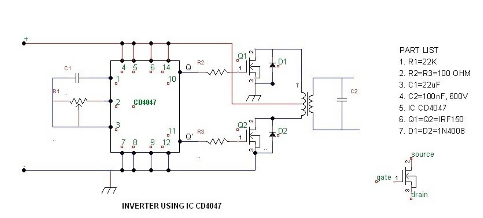
Of all the components that you need to build the system, the role of two components – CD4047 multi-vibrator and IRF540 MOSFET transistor deserve special mention.
The CD4047 multi-vibrator manufactured by Texas Instrument consumes very low power. The system is designed on a way to work both as monostable and astable multi-vibrator. Furthermore, it also operates on gatable or free running mode and provides pretty descent stability in frequency. CD4047 has the power to generate duty cycle of 50%, which actually creates the pulse.
The IRF540 MOSFET transistor is used in this development is because of its capacity for high switching and a current range which can e used for making any inverter from 100 watt to 500 watt.
Developing the System
Referring to Figure 1.0, the 12V battery is connected to the LED diode. The battery is also connected to Pin 8 of IC4047 i.e. the power-supply pin or VCC, and is also further connected to Pin 4 and Pin 5 which works as astable and complement of IC4047.
It is important to note here that the diode will not be able to produce any reverse current. The LED in the circuit acts as a battery indicator to see if its working. The CD4047 IC, in this development will function as astable multivibrator mode.
To make the multivibrator mode work you need to get one capacitor, which need connection between Pin 1 and Pin 3. The Pin 2 is further connected to a variable resistor and a resistor in order to update the output frequency of the IC. The rest of the pins should remain in grounded mode. Pin 10 and Pin 11 are connected to IRF540 mosfet gate. Both these pins also referred as Q and ~Q generates duty cycle of 50%.
In order prevent loading of the mosfet the output frequency has its connection to the mosfet via a resistor. The AC current, which is generated by the two mosfets behaves like two electronic switches. The current from the battery is enabled to move upper or positive half of the transformer’s main coil via Q1. This is done on a situation when Pin 10 gets high and lower or negative half is attained by the opposing current flow via the primary coil of the transformer and when Pin 11 is high. Therefore, the power gets generated by switching the two mosfets.
The AC power is further supplied to step-up the transformer’s secondary coil from where we receive the higher AC voltage. The Zener diode on the other hand enables bypass the reverse current.
For upgrading this circuit to any range between 100 watt to 500 watt inverter, you don't have to change anything just make sure the wattage of the transformer is rated above the required output wattage and the AH rating is 10 times more than the transformer primary amp rating