

The post explains how to build a simple 12V solar charger circuit with boost converter capable of charging 12V battery from a 3V solar panel.
A Solar Charger excellent for Self-Sufficiency
The intent behind this circuit should be to achieve a Solar Charger 13.6V supply with low price. For this reason the project is introduced as a hobby. We have employed an output circuit more streamlined compared to a conventional photovoltaic system design and driver transistor is "low voltage". The two of these elements offer an increase in efficiency by 20% in the Circuit Solar Charger on Conventional solar set up.
Circuit means knowledge of electronics and photovoltaic solar energy.
Solar cell 0.5V @ 280mA
Solar Charger This particular circuit is made to power 12V supplies. Currently the bulk of electronic devices are created to work with a voltage of 12V. With the higher increases of LED lights there isn't any obstacle by somebody wanting to choose to live using a low voltage supply which enable it to take pleasure in electronic delights of living in the city.

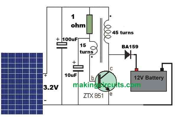
Circuit diagram 12V Solar Charger
12v solar charger circuit
Circuit advantage versus Conventional Photovoltaic Solar Charger Set up
The most important downside of solar energy is obviously precisely the same sunlight! The sun will never glimmer all day and night. Our eyes adjust to variations in the level of the sun, but a solar panel reacts in a different way.
When the sunlight offers solar radiation at reduced strength, ie, in the early hours of the morning and later mid-day, solar panel overall performance diminishes. Not just it reduces the power, but the output voltage likewise reduces.
The output voltage necessary to charge a 12V battery is 13.6 V minimum, this means during lower solar strength load turns into zero.
Solar Charger Circuit demonstrated beneath doesn't work wonders yet offer a a reasonable output with low voltages.
The additional benefit of Circuit Solar Charger to a conventional photovoltaic system is minimal expense in solar panels. You don't actually have to purchase a 12v panel. A few solar cells will probably be appropriate. You can even make use of a faulty 12v panel. Occasionally a 12v panel can be broken by unfavorable reasons, if one or two of the cells does not produce a voltage, the cells can be detached and connected with the circuit. This will likely reduce the output voltage, however the inverter will instantly adapt.
How the simple 12V solar charger circuit with boost converter Works
Solar Charger circuit is essentially established by a blocking oscillator. It offers 45 turns in the primary and 15 turns on the feedback of the inductor. Not any side as primary constitutes a high voltage throughout section of the cycle, and this voltage is supplied to the output through a high-speed diode to generate the output. The output voltage consists of high voltage spikes and should never be tested without load attached to the output. In this situation, it is for charging the battery. Feeding the peaks at 30mA current prototype may be used as a starting sample and as battery voltage goes up, charge current is minimized to 22mA.
The transistor is switched on by way of the base resistor 1 ohm. This leads to current to stream in the primary coil and creating the magnetic flux. This flow slices the turns of the coil and constitutes a feedback voltage in the coil which activates the transistor harder. This carries on so that the transistor is completely on and at this stage, the magnetic flux in the transformer core may e at its optimum level.
The magnetic flux in the transformer core starts to fail and this constitutes a stress on feedback loop causing against the resistance of 1 ohm such that the transistor turns off.
The transistor consistently turns off until it eventually is totally off.
The magnetic flux causes a voltage break in the primary coil. Since the transistor is turned off during this period, we are able to consider it to be stripped away from the circuit and the coil is linked to a high-speed diode. The power created by the coil goes by via the diode and presents itself at the output as a high voltage peak. This high voltage spike additionally includes current and consequently delivers the energy. This electricity is provided with into the load and in our scenario all of us discovered that the Solar Charger is charging the battery circuit 12V.
The smart section of the may be the generation of the high voltage. Whenever a magnetic circuit (primary coil is wound on a ferrite rod and this is called a magnetic circuit) collapses, the voltage created in the clearance is determined by the standard of the magnetic circuit and also the rate at which it sinks. Strain can be 5, 10 or even 100 times more than the applied voltage and this is the reason why we have used.
This is only among the occurrence of a magnetic circuit. The magnetic flux constitutes a voltage fall in every turn of the coil and the actual voltage is determined by the volume of flow existing and the rate of collapse.
The 100u via the solar panel is built to reduce the impedance of the panel in order that the circuit can function as efficiently as possible.
The simple 12V solar charger circuit with boost converter is categorized as being a low impedance. The low impedance arises from the point that the transformer is attached straight to the primary with the entrance in the course of part of the cycle.
The primary resistance is merely a fraction of ohm impedance and is only some ohms as confirmed by the knowledge centered 150mA @ 3.2v. When the battery is attached to the circuit, the current is substantially increased. The 150mA is due to the constraint of the solar panel.
The circuit needs a large power of the same cycle. If the current average is 150 mA, the instantaneous current is often as 300mA or even more. The panel struggles to deliver this power and thus looking for a storage device called electrolyte to compensate current peaks.
The 10u works in a similar fashion.
Both of these components help to make improve efficiency of the design considerably.
You will observe that the battery receives the charging voltage transformer as well as 3.2v solar panel. In the event the battery voltage is 12.8V (voltage in the course of charging) power transformer will probably be corresponding to 9.6V / 12.8V and energy of the solar cell is the same as 3.2V / 12.8V. Quite simply, the battery power is going to be supplied based on the voltage of each supply.
Solar Charger regulator circuit without Load
Our Solar 12V Charger Circuit doesn't have any charge controller. This characteristic is absolutely not necessary with a slower charger. The charge current is so reduced battery never experience an overload.
This is how functions: Once the battery is charging, a small amount of voltgae goes up over normal battery voltage. This is known as "floating charge" or "float voltage" and it is because of the chemical reaction inside the cells, which includes the truth that it bubbles. When the battery gets to the level of ALMOST completely charged, the voltage increases further more and this boost is detected by a circuit which stops the charger.
Solar panels in parallel or in series?
The most significant concerns in interconnection photovoltaic solar energy is whether to hook up the panels in parallel or in series.
The majority of individual pv cells are manufactured from small pieces of solar stuff linked collectively and put through an intensification of the plastic material cover of the light. The output of solar cells utilized in the prototype and 0.5v 280mA (with glowing sunlight). The circuit features a minimal working voltage of approximately 1.5 V therefore any voltage in addition will certainly generate an output. Within our circumstance, cells should be attached in series to get the very best overall performance.
Transformer
The primary coil possesses 45 turns of wire 0.7 mm in diameter on a ferrite rod 10 mm. Wind 40 turns, closely wound, this becomes the stick after which 5 spiraled back to top. Twist the two ends with each other to keep the coil it is in place.
By doing this is called a transformer. It is an oscillator associated with a transformer or flyback function block. The output is obtained through the primary through a high-speed diode.
The oscillator will simply run when the coil is coupled in the proper way. The correct form is displayed in the diagram, with the start of primary and secondary, as proven in the diagram. For this to be effective, both windings has to be absorbed in the exact same direction.
It is possible to track the start and finish of each coil or just hook up the transformer and see if it performs. Otherwise, reverse the arrangement connectors (reverse only one connection - not necessarily both). Absolutely nothing may be damaged when attempting this method as the solar panel would not supply adequate current to ruin the transistor.
Transistor
One of several specific highlights of this specific layout is the driver transistor. It is among the new style of transistors possessing a low resistance emitter, when they are saturated. Additionally it is capable of handling a high power (3 amps) and very peaks of 20 amps. If utilized in a saturation rate, excessive like this, the deficits in the transistor are extremely small and do not require heat-sinking. Some other transistors might work, nevertheless the transistor 851 ZTX 6mA included with the current output because of its attributes.