This first easy circuit will permit you to figure out the value of an unidentified capacitor through a 'Bridge' principle. The exciting portion of the operation is to the right of T1, the other portion of the circuit, which includes Q1 is merely an audio oscillator.
How it Works
T1 is a small transistor output transformer around. 500R CT to 8R. Linked as displayed, in the circuit is recognized as a Hartley oscillator, C2 transforms the primary of the transformer right into a tuned circuit functioning in the audio range while C1 feeds back section of the signal to maintain oscillation moving.

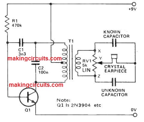
The result of all this is certainly to create an audio signal into the secondary of T1. Now let us have a case in which the two capacitors are of identical value and also the resistance in RV1 among x -y and y -z would be the similar; it's possible that the voltage at y and at the junction of the two capacitors would be the very same certainly nothing will probably be heard in the earpiece.
Believe seeing that our unidentified capacitor is half that of our identified. A larger amount of the signal will probably move across our known component, the bridge is upset and a signal will likely be heard in our earpiece.
On the other hand, if x -y is twice y -z, balance will one more time be accomplished and absolutely nothing will probably be heard. It ensues that if a pointer knob of RV1 is marked in ratios, we will be capable to calculate the value of nearly every capacitor provided that we utilize our reference component one that is amongst ten times and one -tenth of the not known; the reason being it is just practical to mark out ratios of 10 to 1.
This is simply not as much of a issue as might very first be thought of as values among 1p and 100uF could be examined employing four standards - these are generally 10p, 1n (100pF),100n (0.1uF) and 10uF.
Nevertheless, measuring low capacitance may very well be incorrect as a result of strays in the circuit and remember that electrolytic capacitors are generally not usually close tolerance components.
Another Simple Capacitance Meter Circuit
The following capacitance meter circuit includes 4 ranges using full scale values of 5nF, 50nF, 500nF and 5µF, which allows it to be employed for testing a large number of capacitors.
It may not be useful for assessing large value electrolytic capacitors, but since these could be inspected reasonably easily with the help of regular multimeter this may not be a critical downside.

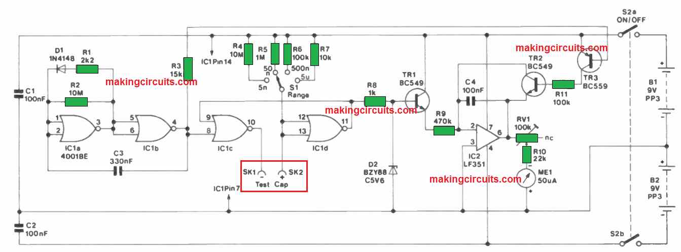
Even though device provides a fairly simple circuit it really is competent at outstanding precision only if it is calibrated appropriately. No specific tools (aside from a single close tolerance capacitor) is necessary to be able to calibrate the meter.
The circuit is dependent on a monostable multivibrator that is created around a couple of CMOS 2 input NOR gates (IC lc and 'Cid) and works by using a conventional arrangement.
The capacitor under test works like the timing capacitor for the monostable, and the timing resistor is one of four components (R4 to R7) that provides the device its 4 ranges.
The monostable's output pulse duration is relative to the test capacitor value, and certain ways of switching the pulse length into a equivalent meter reading is necessary.
This is accomplished by providing the output pulse to the input of a Miller Integrator. The miller integrator is built around a standard operational amplifier type that is designed using IC2. The fundamental working of the circuit is to present an output voltage that runs negative in a linear rate while input pulse is available.
Put simply it gives the essential pulse length to voltage conversion, and RV1 could be fixed up in order that the unit offers direct readings in capacitance. R8 and D2 efficiently stabilise the output pulse voltage of the monostable to ensure that fluctuations in supply voltage tend not to drastically impact the calibration of the capacitance meter.
The output pulse length of the monostable is not going to be supply centered, and it is not important to employ a regulated power supply for this portion of the circuit. IC 1a and IC 1b work like a low frequency astable circuit which supplies a short negative output pulse around once for each second.
R1 and driving diode D1 are accustomed to provide the astable circuit the necessary nonsymmetrical output waveform. The falling edge of this signal is employed to activate the monostable and routinely take fresh readings at around one second intervals.
C4 should be discharged prior to a fresh reading is obtained, and this is achieved by TR2 and TR3 that are biased into conduction throughout each of the short negative output pulses from the astable circuit.
Improved and Much Accurate Capacitance Meter Circuit
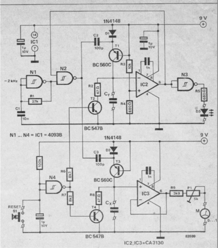
The second design is a simple yet accurate analogue capacitance meter circuit. The significance of a capacitor depends upon giving it exactly the same charge as a reference capacitance followed by evaluating the voltages between these.
This utilizes the method C = Q/V where C is given as the capacitance in Farads, Q would be the charge in Coulombs and V is the voltage in volts.
If as a result two capacitances possess identical values, their magnitudes may be determined once the voltages around these are identified. A couple of circuits guarantee that reference capacitor Cr plus the capacitor being calculated, CX, are charged evenly.
The proposed analogue capacitance meter circuit intended for Cr involves C2, D1 as well as T1 and that with regard to CX of C3, D2 and T3.
Whenever the output of gate N2 goes up, the charges of capacitors C2 and C3 tend to be shifted toCr and Cx by transistors T1 and T3 correspondingly.
While the output of N2 lowers, C2 and C3 recharge by means of diodes D1 and D22. Gate N2 is governed through astable/ multivibrator N1 that works out at a frequency of approximately 2 kHz: Cr and CX tend to be consequently charged at that frequency.
The voltage around Cr is actually investigated by C2 using a reference voltage produced by the power supply through R3/R4. As soon as the voltage around Cr surpasses the reference voltage, comparator lC2 inverts which usually prevents N2 to result in N3 to be able to illuminate LED D3.
The values on Cr and CX at the moment are the same and the meter shows simply the amount of the voltage through Cx varies from that of Cf. Buffer IC3 offers a significantly high load impedance for Cx.
Pushing reset button S1 leads to equally Cr and CX to discharge through T2 and T4 correspondingly, followed by the charging course of action restarts and the circuit becomes ready for another measurement procedure.
The analogue capacitance meter circuit can be calibrated by making use of a pair of exactly the same 10 nF capacitors for Cr and CX. Push the reset button and, as soon as the LED illuminates, fine-tune preset P1 to present a meter deflection of precisely 1/10th of total scale deflection (fsd).
This particular display on the meter relates to 1 x Cr. lf, for that reason, Cr = 100 nF and CX = 470 nF, the meter will probably display 0.47 of fsd.
To make certain an acceptable rate of charging periods in the course of a measurement, Cr and CX-should not possible be lower than 4.7 nF.
In order to determine smaller sized magnitudes, capacitors C2 and C3 must be minimized. As an example to make it possible for a capacitor of 470 pF being tested, C2 and C3 should be 10_ _ 20 pF. The circuit is moderately specific for magnitudes of CX around 100 pF.
More than this value the meter response will be impacted by leakage currents. To be able to determine capacitors as high as 100uF, the magnitudes of C2 and C3 needs to be raised to 1uF. Current utilization will be nominal making sure that a 9 V battery can be a suitable power source.