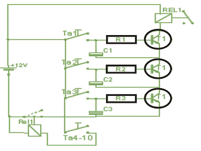
This simple code lock circuit can be used to lock doors by pressing a 3 button keypad.
As the simple code lock circuit consists of extremely few components it is also very cheap to build, the code is a 3-Step with no digits it may be repeated, for eg. 123 or 473 are OK, but not 112 or 767th This is the simple version of the circuit can be easily found in the code by simply try after some time.
How the Circuit Works
This circuit I had in my mind for quite some time in the past, just threw it together this weekend.
The assorted-resistance value may seem a little strange I just selected whatever the next-best resistors I had in my junk box.
The values are therefore only indicative and may be chosen as per individual comforts.
With these values, you have to type in the code pretty quickly if you do not want to press all 3 buttons simultaneously.
The simple code lock circuit is assembled as per the plan shown below and may be the easiest over a piece of prototype board.
The switches are not soldered to pads, the shown are only for 3 selected out of the 10 keys.
Therefore you solder only the capacitors, resistors, transistors, and the relay, the places where the switches are required could be just ways you can put solder pins.
The 10-button keypad is supplied on the same pole with + voltage, which include the three contacts with the numbers they want to use as the code to be connected to the solder pins. going from bottom to top, ie. In the present diagram the Code is 321
The remaining contacts are soldered to each other and connected to the relay No.2, which locks the circuit.
If you are having difficuty understanding, it's going from the keyboard 5 wires away (3x code button + 1x every other button + 1x positive voltage)
This is necessary because otherwise all the switches could be pressed simultaneously, and thus the code would be triggered.
