If you are looking for a delay ON timer circuit that may be really simple yet efficient, then this tiny design will help you achieve the requirement.
Using only BJTs for the Delay ON Processing
Referring to the circuit we can see that it's built around just a couple of general purpose BJTs BC547, and a few other passive components. The relay here is used for toggling the connected load after the intended delay ON is elapsed.


The 2M pot or preset and C1 determine the delay length and can be tweaked appropriately for achieving the desired delay time across the connected load via the relay contacts.
The circuit functioning can be understood with the help of the following explanation:
How the Circuit Functions
As soon as power is switched ON, C1 being in a fully discharged state initially acts like a short circuit and the current from the 2M is shunted to ground.
This prevents any current from reaching the base of T1, and it is rendered switched OFF during power switch ON, and correspondingly T1 being switched OFF allows T2 to switch ON, and this causes the relay to switch ON when the circuit is powered.
Now, as time begins lapsing, C1 begins charging via the 2M pot, and eventually the voltage C1 reaches to a level where it is enough to switch it ON T1 fully.
This in turn causes T2 to switch OFF along with the relay, after the set delay has elapsed completely. The procedure successfully ensures the implementation of the intended delay ON timer function.
When this is executed the load connected across the N/C of the relay is switched ON with the required delay ON implementation.
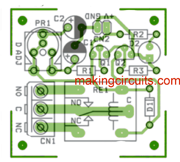
The PCB design and the layout is shown below: