

The most straightforward form of intercom circuit would be to use a microphone feeding an amplifier which in turns feeds a speaker at the other end.
When the remote end wished to contact the first station they would speak into a microphone which would drive a second amplifier at the remote end and this would be fed along the wires to the local station.
However to avoid a "howl-round“ occurring it would be necessary to ensure that only one end was speaking at the same time. Since this facility cannot easily be incorporated, we can make considerable economies in the circuitry by using just one amplifier and two speakers.
The Circuit Design
The amplifier and one of the speakers is situated at the master station. At the remote station (often known as the "slave station") is situated only a speaker and a second battery.
Since we are using two speakers, which of course have low impedance, it is necessary to design a special amplifier which has both low input and low output impedance and also (tor different reasons) one contact of each of the speakers should be common to the negative line.

How it Works
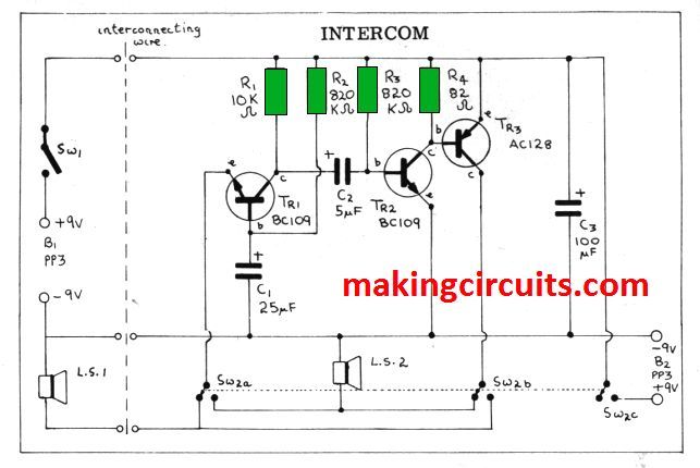
Loading at the intercom circuit we can see that the slave unit comprises simply of PP3 battery, a loudspeaker and an on-off switch. The negative side of the battery is connected to one end of the speaker and three wires lead to the master unit.
These three wires can be of considerable length since there will be very little loss as the source impedance of the speaker is low, similarly with the battery; it needs a very long length wire before the d. c. resistance is enough to cause any appreciable voltage drop.
In the standby position, with neither station making a call, SW1 in the slave unit is open. When the slave wishes to call the master this is closed and Bl applies voltage to the amplifier via one oi the interconnecting wires. In the master unit, on standby, SW2 is in the position shown and so the slave‘s loudspeaker is connected to the emitter of Tr1.
This transistor is connected in the common base mode and the typical input impedance of a transistor so connected is low about 50 ohms typical. This then closely matches the impedance of the speaker which (as will be seen from the component list) should be between 35 and 80 ohms.
These impedances are quite common in small speakers, Large speakers could be used, they are generally more efficient, but this will make construction difficult. The output of the first stage is coupled via C2 to a further stage of amplification, Tr2, which is connected in the common emitter mode.
The collector load of this transistor is quite low and must also be accurately chosen. This stage connects to Tr2 which is an inverted PNP transistor. The collector of this goes via the switch to the local speaker and in this way the speech at the remote end is heard without any local switching being done. When the master wishes to call the slave unit, the switch SW2 is made.
This firstly applies the local battery to the amplifier by SW2c. Secondly the output of the third transistor is switched to the remote loudspeaker and thirdly the local speaker is applied to the input of the amplifer. The same operation occurs but this time the speech locally originated is heard in the remote loudspeaker.
The reason for referring to one of the units as the "master" is because the switch SW2 overrides the slave‘s switch. If the remote end makes the switch while the master is talking, all this does is to apply two batteries to the amplifier and no change takes place.
The current consumption of the simple intercom circuit is quite high but this does not matter for an intercom is not likely to be used continually. Both of the switches should be spring loaded so that while talking the switch has to be held on; when the conversation has finished the switch is released and the unit is turned off.
The value of R4 is somewhat critical. This controls the bias on the third stage and it is important that the quiescent current is of the right level. If too low there will be severe distortion, if too high the quality will be lovely but the transistor will be drawing very high currents which will run the batteries down very quickly or even damage the transistor.
The value of B2 ohms is a typical one but its actual value should be found by experiment; if necessary a variable resistor can be used in its place.
The value should be the lowest one that is compatible with acceptable speech quality but should never be higher than 20mA if measured on a meter.
Even this quiescent is fairly high and for this reason Tr3 should be fitted with a heat sink.
Home Intercom Circuit
This specific home intercom circuit works with a simple three transistor amplifier which provides a significant high class output (by intercom standards) as well as a sufficient output power of a few tens of milliwatts.

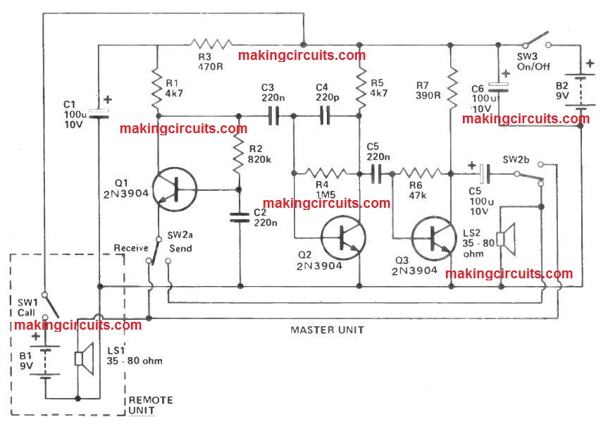
As is standard process along with intercom layouts, the loudspeaker in each station likewise doubles as a type of moving coil microphone when 'sending'.
The position of SW2 decides perhaps the slave unit is 'sending' plus the master station receives, or the other way round. Ideally this would be a spring loaded switch which often instantly returns to the 'receive' position when discharged.
This permits the remote unit to contact the master one if the user shuts SW1 in order to link power through B1 to the amplifier, and then communicates into the microphone in order to draw in the attention of the individual at the master station.
If SW1 is not a spring loaded switch, it may be left in the 'send' mode, stopping the remote station from calling the main one. SW3 is the standard on/off switch at the master station.
The amplifier is a three phase unit capacitive coupling among stages. A standard base input stage (Q1) is employed as this provides a low input impedance.
This really is desirable as it minimises stray pick-up of line hum sound and radio disturbance in the linking cable, and in addition it provides a good match to the microphones.
These kinds of two stages are generally uncomplicated usual emitter amplifiers. C4 rolls off the high frequency response of the home intercom circuit and this also assists firmness.
Additionally, it may assist to avoid RF breakthrough. The prototype was attempted along with hooking up cables around around 10 metres roughly long, and provided completely great outcomes.
It will function with for a longer time linking cables if required. A three conductor linking cable is essential.
2-Way Intercom System
One of the most useful ways to deliver a message without interrupting your work or walking the distance to deliver the message personally would be via an intercom circuit.


Figure 1 describes an electrical schematic of a two-station intercom circuit. While being extremely simple, it has also components that are unique and not found in other commercial applications.
Only a single IC is found per unit and one usual spring-return toggle switch functions to actuate the TALK/LISTEN function. There will be no current drain from the battery when the intercom is placed in the normal listening position. Furthermore, just two cables can be utilized as the transmission line between the units. What is more interesting is you can attach up to four units within the two-wire circuit.
How the Circuit Works
A tiny omni-directional electret-microphone element detects the audio signal and eliminates the necessity for a pairing transformer. Furthermore, the need for extra switch contacts for toggling a single pickup/output component between the input and output circuitry is eliminated. In a standard intercom, one speaker and a matching transformer is applied for both sound detection and output chores. But in our method, the circuit works just as well with cost-friendly components and a simple build.
Through C1, the input audio signal passes to the volume potentiometer, R2. After that, it is channeled to the input of the IC amplifier (U1 – an LM386 low-voltage audio-power amplifier). Then, the amplifier intensifies the signal about 200 times. The output of U1 is attached via C4 to one contact of switch S1-b. From this position, the signal is directed to the other intercom speakers through the double-wire interconnecting cable. An individual 9 V battery powers each intercom.
When idle, the intercom unit is in the LISTEN position with their speakers attached together via the two-wire cable. In this state, there is no power applied to the either one of the two stations. The moment one of the intercom stations is switched to the TALK position, the battery will be connected, and the amplifier’s output is supplied to the intercom speaker. This happens at the end of the com-link through the two-wire cable.
Construction
Construction of the intercom is pretty straightforward. Given the smaller number of components and an uncomplicated design, you can easily construct the circuit the way you like it. The com-link is an apt project for PCB construction and helps you to understand its layout. Alternatively, you can also use a perfboard and push-in pins. Whichever your choice is, it is recommended that you use IC sockets for the LM386 amplifiers.
This circuit can be contained in any enclosure. However, using a plastic case is much cheaper and simple to work with. You just need to attach the electret-microphone elements, speakers and switches facing forward. Most likely you will only need to assign the talk volume once so R2 can be placed within the case too. In this way, you could prevent the drop of gain to zero.
How to Test
During the testing phase of your 2 way intercom circuit, just connect the two stations together using a two-conductor run of wire. It is important to maintain a distance of at least 10 feet to alleviate acoustical feedback. After that, you must set R2 to its mid position before placing the switch of either stations in the TALK setting. Loudly speak into the microphone and regulate R2 for a clear output level in the other unit’s speaker. Finally, you must do the same but in reverse using the other intercom.