

In this post we will learn how to build a few SCR applications circuits such as battery charger, code oscillator, rain alarm, automatic night lamp etc.
An SCR or a silicon controlled rectifier is a semiconductor device which conducts a relatively larger voltage and current across its anode cathode terminals in response to a low voltage current triggers act it gate terminal.
The following figure shows a standard SCR pinout diagram


Introduction
Back in olden days, in case you wished to control a motor’s speed, you needed a “brute force” rheostat having a control knob the size of a little wheel. It typically required an hunk of a man with a pair of hands on the wheel to decelerate or accelerate the electric motor.
After that solid state devices arrived, and voltages decreased until you could possibly press a contact rather than pull an arc. And also the steering wheel sized rheostat transformed into a little control you could handle using two fingers. To a great degree, that had been due to invention of the semiconductor device known as silicon controlled rectifier, or the SCR.
Fundamentally, it is actually a diode internally but having an extra lead that is applied as (and is named) a gate. Thanks to the SCR, small voltages are able to activate significantly larger voltage levels, without the need of relays that actually facilitate just couple of regular changeover contacts.
SCR actually enables you to control a complete range of voltages. As time (and technology) advanced, fresh applications are being identified for the adaptable device, and we’re pleased to make available a variety of these assorted SCR applications circuits through the following article.
SCR Tester Circuit
This useful little SCR circuit can provide you with a visible indication, is a one afternoon project, and it is simple to put together. Figure 1 exhibits a 3 -amp, 50 -volt SCR and a experiment circuit. A fixed resistor works extremely well for R1. Points G (gate) and K (cathode) are momentary contacts in order to quickly be opened. If R1 is a fixed resistor with a few 100 ohms, when K is closed, the lamp won’t illuminate.


If G is also closed, the lamp switches ON to its 100% power. The lamp continues to be illuminated even if G is opened up again. However if K is opened, even briefly, the lamp never lights up again even if K is connected. It lights up when G is switched ON. This shows the “on” and “off” functioning of the SCR. If R1 has larger ohms, say around 50,000 ohms, it is possible to attach a meter at G to exhibit the gate current (IG). A tiny gate current runs which increases when you decrease the R1 value. At a certain given value of IG, the SCR starts to allow electricity flow and the lamp illuminates. By using a regular 3 -amp, 50 -volt SCR, conduction triggers at a current level of say around 0.5 mA.
Anyone can easily build an extra test by delivering the current through an variable voltage source, permitting a person to figure out the SCR’s switch -off level. Closing K and then momentarily close G. Bring down the anode -to- cathode source to about 2.0 volts, revert 12 volts, and observe how the lamp stays illuminated. Keep reducing the volatge to around 1.0 volt and do the procedure again then verify. You are going to identify a point, in which when the supply is decreased below the controlling level, the SCR is not going to trigger even if complete voltage is delivered. It has reverted to the “switch OFF” condition.
Simple SCR Burglar Alarm
The burglar alarm circuit is attached to the SCR anode and gate. Any type of slight pressure on the mat switches ON the contacts of the mat switch, that switches ON current to the SCR gate, triggering it to. With the SCR switched ON, a route to ground is supplied by means of BZ1 (a 6- to 12 -volt bell) and SCR1, resulting in BZ1 to sound the alarm. The bell carries on ringing, even if the intruder tries to jump out of the mat. To switch the security alarm off, it becomes necessary to physically chuck switch S1 to interrupt the circuit. In the daytime, while customers are busy moving in and out, you can just disconnect the switch and the alarm will be impaired until finally you toss the switch on once again, to equip the circuit.

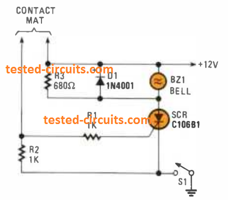
Diode D1 is actually to safeguard the SCR from reverse EMF of the bell coil winding. While the vibrating contacts of the bell disconnect, the circuit breaks. Resistor R3 keeps a stable current via the SCR, maintaining it from returning to the switched OFF condition. We actually don’t require R2 when leakage in the alarm circuit is negligible. This sort of leakage may possibly present ample current to induce the SCR triggering, but R2 perceives to it that this sort of leakage would need to be too big for the false triggering to take place. Once the mat is walked on, R2 is just along the supply and it has absolutely no impact. Power input of some other level could also be tried.
SCR Rain Sensor Alarm
Rain falling on the panel decreases circuit resistance right up until gate current activates the SCR circuit. This switches ON the tiny buzzer, that continues to be on before the water dries or S1 is opened up. Resistor R2 delivers ample current to maintain SCR1 switched ON.

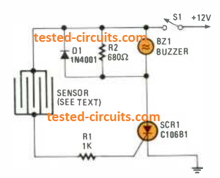
You may also utilize the circuit to run an underground pump whenever water level touches specific level by attaching a switching relay to the circuit instead of the buzzer. Using the similar approach, you might connect it to some motor and utilize it for whatever right from shutting windows automatically when rain begins, to elevating a collapsible cover on the car
Battery Charger using SCR
Its a chilly air around. You enter your car, and you push the fuel peddle a few times, switch on the combustion key, and the nearly all you obtain is actually a “click.” The battery is as lifeless as a iron nail. Figure 4 is a trickle battery charger whose output level drops as the battery voltage goes up. Good, right? As the battery charge nears the full level, the charging current gets shut down automatically. Hook it up, and return back to your seat where you find it to be fine and comfortable.


The mains transformer, T1, a bridge circuit; and SCR1 are specified for the optimum current and voltage necessary. Work with a 12.6 -volt transformer, competent at providing 3 to 5 amp current. When full charge level is reached, resistor R1 and diode D1 activates SCR1 to ensure the full charging rate is initiated. The voltage around R6 and R3 is actually comparatively minimal, therefore D2 does not switch ON; which causes SCR2 to be off.
The voltage where SCR2 triggers is defined by potentiometer R6. Any time D2 begins conducting gate current to SCR2, the SCR activates, forcing diode D1 to reverse bias. The voltage for D1, driven via R1, falls practically to zero volts. This prevents SCR1 from activating. The result is gradual and the triggering angle of SCR1 is lowered while voltage goes up. It is possible to place a current limiting resistor, meter, or fuse at R2.
Code-Practice Oscillator.
This SCR circuit looks straightforward as it is. In Fig. 5, the charge across Capacitor C1 rises by means of resistor R1, and as soon as the charge level reaches the gate triggering level as set up by potentiometer R2, the SCR is activated.

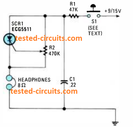
Current runs by means of the SCR and headsets, discharging the 01 capacitor. The anode voltage and current decrease to some minimal level therefore the SCR ceases to conduct, and this ON/OFF cycle keeps repeating. Resistor R2 allows the gate voltage across 01 to be modified, which helps vary the frequency or tone.
SCR Controlled Automatic Lights
I developed this basic SCR circuit (See Fig. 6), which can be governed with a light dependent resistor, LDR (R3), that activates a single hall room light once the room gets almost dark. This automatic night lamp switching may be actually enough to cause a potential robber believe that someone is really present in the house. When the day breaks and the sunlight arrives, the home light is turned off automatically. Is actually sufficient although not really too perfect.

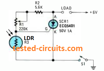
Given that potentiometer R1 works like a level of sensitivity control, nearly every LDR fits the project. The one that had been chosen in the diagram had a resistance of approximately 1 megohm while it’s totally dark . As soon as light is detected by the LDR, its resistance falls to some hundred ohms.
When light source illuminates the LDR, the SCR gets switched OFF across the gate. However once the illumination level hitting the LDR declines, the SCR triggers, and the circuit gets completed. We advise that considering that the SCR will likely be controlling a lamp, it might be best if you work with a relay to switch the lamp, instead of trying to drive the mains lamp straight from the SCR. Potentiometer R1 defines the sensitivity of the circuit.