


A Smoke detector circuit is an essential system when it comes to maintain safety precaution for any establishment. Having a smoke detector installed makes life easy to save your establishment from any fire attack.
Smoke detector is common these days and this project aim to detail the process to building the alert system.
Smoke Detection Logic
Before we start let us give some few insights on the smoke detector system. Smoke detectors are mainly of two different type: Ionization smoke detectors and Photoelectric or Optical smoke detectors. The photoelectric detectors have a light source and a photocell like light detector. The photocell works as with the falling of light into the system. During smoke the light coming from the photocell gets blocked, which helps to generate the signal. On the other the ionization detectors are made of two electrodes and an ionization body with ions into it. On a no-smoke situation, these ions roam freely and the electrodes lie in the normal state. When there is smoke these ions are unable to move freely and the electrodes cease to work. Though the conductivity may change depends upon the manufacturer of the alarm system, but theoretically the process has no difference. Therefore, the alarm system can be developed upon measuring the output of the smoke detector.
To build the proposed system, we have used Smoke / Gas Sensor MQ-2. The device is highly sensible to methane, propane, butane hydrogen, LPG and other combustible gases. The system also has two electrodes. They are made of Aluminum Oxide and a heating system made of Tin Oxide.
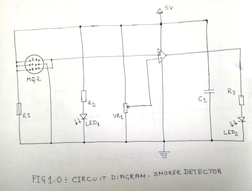
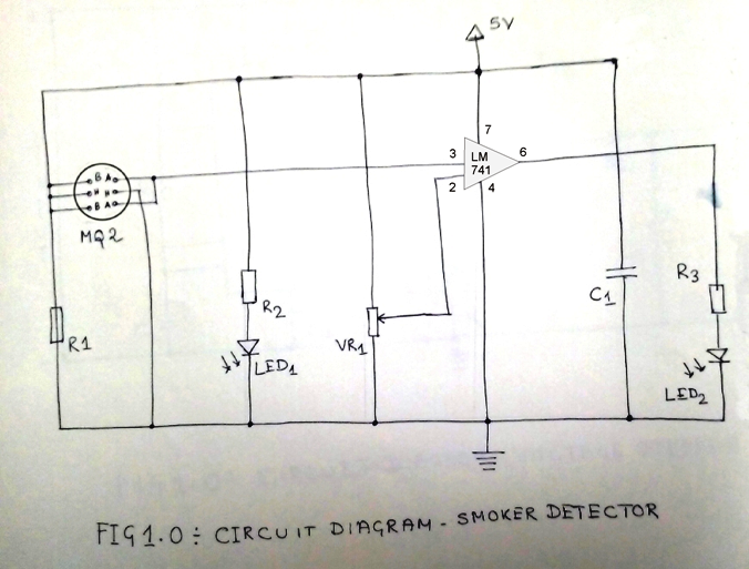
The following diagram in Figure 1.0 is the circuit diagram of our project:

How it works?
Building a smoke detector is cheap, yet very much effective. To develop the system, we have used LM358 comparator is used beside the MQ-2 smoke sensor. Here the LM358’s inverted terminal is interfaced with POT to so as to adjust the sensitivity of the circuit. The output generated by LM358 uses a LED as an indicator. As an alternative for the alarm you can also use a buzzer. Further, the non-inverted terminal of LM358 is interfaced with the smoke sensor’s output.
During clean air, the conductivity between the electrodes remain less because of the resistance order working on 50KW. Here the value of the input of the inverting terminal remain higher than the input of the non-inverted terminal, which keeps the LED in OFF state.
When there is heavy smoke because of fire, the sensor gets filled with the smoke and the sensors resistance drops to 5KW, which increases the conductivity between the electrodes. This process enables high input of the comparator’s non-inverted terminal resulting to high output. With this situation the LED turns ON and the fire alarm starts ringing.
Building the smoke detector circuit is simple, however, please ensure to preheat the heating element of the smoke sensor to sense smoke or gas. Also as a word of caution, do not touch the sensor when its ON because in this state the sensor gets very hot because of the heating coil. To control the sensitivity of different level of smoke, you can adjust it with POT.Furthermore, you can also use buzzer instead of LED to generate smoke alarm.