


Here we talk about a simple solar charger circuit. It takes power from a 20V, 1A solar panel and then charges a 12V battery. We are using a 7812 voltage regulator IC, three 1N4007 diodes, and a 2.2kΩ resistor to make sure the charging happens safely. Now let’s go step by step.
Circuit Diagram

Main Working Principle
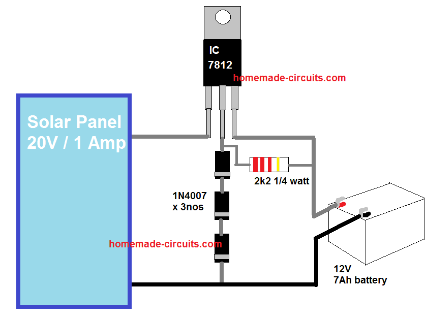
We have that 20V / 1A solar panel first, which gives raw DC, just direct panel voltage, and then that raw line goes into LM7812 voltage regulator, or 7812, which then holds the voltage near 12V at its output.
From that output, the line goes toward the battery through one 2k2 resistor and one 1N4007 diode, while battery negative stays directly with panel negative, so now the charging line simply becomes panel positive to 7812 then resistor and diode side then battery positive.
Why 4 Diodes Are Connected at the Ground Pin
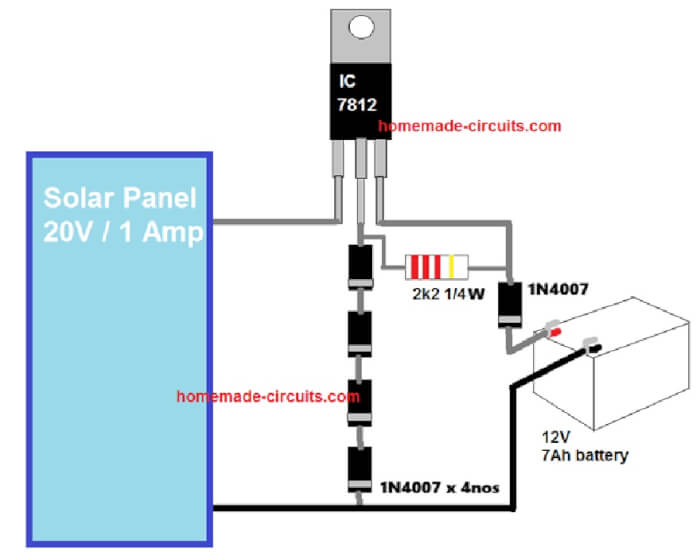
The real trick happens at the regulator ground pin, because 4 series 1N4007 diodes are placed between the 7812 ground pin and actual ground which means each diode lifts that ground by around 0.6V, so four of them together make near 2.4V.
Since 7812 always keeps 12V above its own ground pin, then if that ground rises by 2.4V, output also rises with it, so now 12V becomes nearly 14.4V. However, due to the presence of the output 1N4007 diode, this 14.4V now become 13.8V, which is just about what is required for optimally charging a 12v battery...
So now instead of behaving like plain 12V regulator, the 7812 starts acting like a 14V charger regulator, and that is the clever adjustment here.
Why Around 14V Matters
A 12V lead acid battery usually wants around 13.8V to 14V if floating, although for normal charging then 14.2V to 14.4V is better, so all these five diodes are doing that correction because without them the battery would only find 12V and then charging becomes weak and slow.
Role of the 2k2 Resistor
That 2k2 resistor is there, but practically it does not push real charging current, since at 14V the current through 2k2 stays only about 6.3mA, very small, almost nothing for charging so actual battery current mainly goes through the main output path and diode side.
It still helps a little with regulator reference and startup behavior, but not as the main current path.
Role of the Output Diode
The output 1N4007 near battery is very necessary, because when sunlight goes away then battery can try to send current backward into the panel, and that diode stops it, so daytime current goes forward, night time current stays blocked.
Available Charging Current and Heat
The panel rating is 20V × 1A, so maximum current can reach 1A, but because 7812 is linear, then extra voltage becomes heat, so whatever drops from 20V down to 14V turns into heat inside the regulator.
At 1A, that loss becomes about 5.6W, which is a lot for this small IC, therefore heatsink is not optional, it must be there otherwise the regulator will get hot fast and may shut down or fail.
A medium aluminium heatsink is usually enough here, but without it then trouble starts quickly.
Weak Point of This Circuit
There is no current control, so if battery is deeply discharged then current can rise hard at first, depending on battery condition, and since 7812 practical safe current stays near 700mA with good heatsink, then charging remains suitable only for small battery sizes.
For 7Ah battery, that matches reasonably, because ideal charge current comes near 700mA, so this circuit fits that range, but bigger batteries will charge too slowly.
Capacitors Are Necessary
One more thing, capacitors must be added in real build because without them regulator can oscillate.
At input side, add 0.33uF and 470uF, and at output side add 0.1uF and 220uF, so input line gets smoother and output stays stable.
A 470uF / 35V at input and 220uF / 25V at output works well in practice.
Better Diode Choice
For output diode, better if you use 1N5408 instead of 1N4007, because it handles current better and heats less, though 1N4007 can still survive at 1A if conditions stay normal.
Better Regulator Option
If stronger regulator is wanted, then LM338 is better, because voltage can be adjusted and current handling is stronger, so operation becomes cooler with proper heatsink.
Practical Improvements
You can replace the four diodes with preset adjustment, add 1 ohm / 5W current limiter, add 100nF capacitors, use 1N5408 diode, and place 1A fuse at battery positive, because fuse saves things when fault comes.
Conclusion
This charger works fine if battery is small, sunlight remains steady, heatsink is present, and you watch charging manually, however good thing is that, auto cut off may not be required because 13.8V is below the full charge level of the 12V battery...
So if building exactly this one, then 7812 with large heatsink, 4 diodes at ground pin, 1N5408 at output, 470uF input capacitor, 220uF output capacitor, and 1A fuse, that makes it much safer and more dependable.