

Solar power is massively accessible to us and is free of charge to utilize, furthermore it’s a limitless, endless natural source of energy, simply reachable to everyone. We certainly have talked about easy methods to use solar panels for producing electricity from solar or sun power, in this post we intend to talk about a basic arrangement which is able to allow us to utilize solar energy for working our household appliances.
A solar panel has the capacity to change sun rays into direct current at lower possible levels. For instance a solar panel might be specific for providing 36 volts at 8 amps under optimal circumstances, but we are not able to utilize this magnitude of power for working our domestic appliances, since these home equipment can work only at mains potentials or at voltages in the ranges of 120 to 230 V. More completely the current ought to be an AC and not DC as generally get from a solar panel.
We now have discover several inverter circuits submitted within this blog and we certainly have analyzed how they function.
Inverters can be used for transforming and upgrading low voltage battery power to high voltage AC mains levels.
Consequently inverters may be efficiently useful for changing the DC from a solar panel into mains outputs that will surely power our domestic equipment.
Fundamentally in inverters, the change from a low potential to a moved up high mains level turns into possible due to the high current that’s usually offered by the DC inputs such as a battery or a solar panel. The overall wattage continues to be the same.
For instance if we supply an input of 36 volts @ 8 amps to an inverter and get an output of 220 V @ 1.2 Amps usually means we simply altered an input power of 36 × 8 = 288 watts into 220 × 1.2 = 264 watts. For that reason we are able to observe that it’s absolutely no magic, just changes of the specific guidelines.
If the solar panel has the capacity to produce sufficient current and voltage, its output can be utilized for directly functioning an inverter and the linked household devices and also at the same time for charging a battery. The charged battery can be used for running the loads via the inverter, during night times when solar energy is not found.
In spite of this if the solar panel is smaller in size and not able to produce adequate power, it might be utilized simply for charging the battery, and evolves into effective for operating the inverter only after sunset.
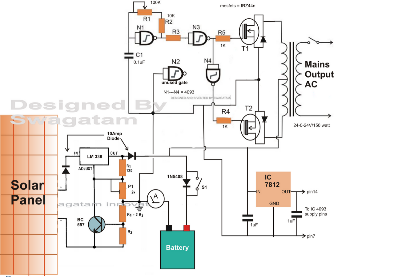
Making reference to the circuit diagram, you can easily experience an easy set up utilizing a solar panel, an inverter and a battery. The three units are attached by means of a solar regulator circuit that directs the power to the particular units after suitable stipulations of the obtained power from the solar panel.
Presuming the voltage to be 36 and the current to be 10 amps from the solar panel, the inverter is chosen with an input operating voltage of 24 volts @ 6 amps, offering a total power of about 120 watts.
A fraction of the solar panels amp which amounts to about 3 amps is spared for charging a battery, meant to serve after sunset.
We also believe that the solar panel is installed over a solar tracker so that with the ability to provide the stipulated needs provided that the sun is noticeable over the skies.
The input power of 36 volts is placed on the input of a regulator which trims it down to 24 volts.
The load hooked up to the output of the inverter is picked such that it does not force the inverter more than 6 amps from the solar panel. From the remaining 4 amps, 2 amps is supplied to the battery for charging it.
The remaining 2 amps are not employed for the sake of sustaining better effectiveness of the whole system.
The circuits are all those which has been previously mentioned in my blogs, you can easliy notice how these are generally smartly set up to each other for applying the needed procedures.
A MINI solar inverter circuit with relay changeover is talked about Right here

For Charging Batteries up to 250 AH
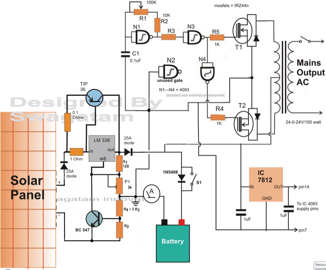
The charger section in the above circuit could be accordingly improved for allowing the charging of high current batteries in the order of 100 AH to 250 AH.
An outboard transistor TIP36 is properly built-in across the IC 338 for helping the essential high current charging.
The emitter resistor of TIP36 needs to be determined correctly usually the transistor may indeed blow off, do it by trial and error technique, begin with 1 ohm at first, then slowly go on lowering it until the needed quantity of current turns into attainable at the output.

Transformerless Solar Inverter Circuit
Sun is a significant and a limitless source of raw power which is accessible on our planet freely available. This power is simply by means of heat, in spite of this humans have found techniques of taking advantage of the light also from this huge source for producing electrical power.
These days electricity is becoming the everyday living line of all cities and even the rural areas. With draining fossil fuel, sun light guarantees to be one of the major alternative source of energy which might be found instantly from any shade and under all situations around the world, free of cost. Let's learn certainly one of the ways of transforming solar energy into electricity for our individual advantages.
In one of my earlier articles I possess mentioned a solar inverter circuit which quite had a basic approach and integrated a regular inverter topology utilizing a transformer.
Transformers as we all know are large, weighty and could become quite annoying for certain functions.
In the existing design I have attempted to get rid of the utilization of a transformer by including high voltage mosfets and by upgrading the voltage by means of series connection of solar panels. Let's research the complete design the with the aid of the following points:
Considering the circuit diagram, we are able to observe that it essentially includes three main phases, viz. the oscillator phase comprised of the adaptable IC 555, the output period comprise of several high voltage power mosfets and the power providing phase which uses the solar panel bank, which can be fed at B1 and B2.


220v, 120v transformerless solar inverter circuit
Considering that the IC are not able to function with at voltages a lot more than 15V, it is well guarded by way of a reducing resistor and a zener diode. The zener diode limitations the high voltage from the solar panel at the linked 15V zener voltage.
In spite of this the mosfets are able to be controlled with the full solar output voltage, which can lie somewhere between 200 to 260 volts. On overcast problems the voltage may decrease to well below 170V, So possibly a voltage stabilizer can be utilized at the output for regulating the output voltage under such circumstances.
The mosfets are N and P kinds which form a pair for employing the push pull actions and for producing the needed AC.
The mosfets arenot specific in the diagram, preferably they needs to be scored at 450V and 5 amps, you will discover many versions, if you google a bit over the net.
The utilized solar panels should purely have an open circuit voltage of around 24V at full sunlight and around 17V during bright dusk periods.


Parts List
R1 = 6K8
R2 = 140K
C1 = 0.1uF
Diodes = are 1N4148
R3 = 10K, 10 watts,
R4, R5 = 100 Ohms, 1/4 watt
B1 and B2 = from solar panel
Z1 = 5.1V 1 watt
Use these formulas for calculating R1, R2, C1....

50 watt Solar Inverter with Charger Circuit
The following post describes a basic 50 watt solar inverter circuit comprising of it's own battery charger and a programmed changeover relay system for switching the battery to the inverter not having solar energy.
The design:
The proposed solar inverter with battery charger circuit mostly contains two phases viz: the 50 watt inverter, and the automatic relay changeover.
In the course of day time for so long the sun light stays realistically powerful, the panel voltage is utilized for charging the battery as well as for running the inverter via the relay changeover contacts.
The automated changeover circuit predetermined is placed such that the connected relay trips OFF when the panel voltage drops below 13 volts.
The above motion disconnects the solar panel from the inverter and links the charged battery with the inverter so that the output loads carry on and operate making use of the battery power.
50 watt Solar Inverter Charger Circuit for Science Project
Circuit Explanation:
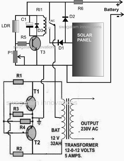
Resistors R1, R2, R3, R4 together with T1, T2 and the transformer forms the inverter section. 12 volts used across the center tap and the ground begins the inverter instantly, nevertheless here we will not hook up the battery instantly at these points, quite by means of a relay changeover phase.
The transistor T3 with the connected parts and the relay forms the relay change over stage The LDR is stored outside the house or at a position where it can feel the day light.
The P1 preset is modified such that T3 just prevents carrying out and removes the relay in the event the ambient light collapses below a particular level, or simply just when the voltage goes below 13 volts. This undoubtedly occurs when the sun light turns into too weak and is not anymore in a position to maintain the stipulated voltage levels.
In spite of this provided that sun light continues to be bright, the relay stays activated, hooking up the solar panel voltage straight to the inverter (transformer center tap) via the N/O contacts. Hence the inverter evolves into workable by way of the solar panel during day time.
The solar panel is furthermore at the same time useful for charging the battery via D2 during day time so that it charges up fully by the time it gets dusk.
The solar panel is chosen such that it by no means produces more than 15 volts even at peak sun light levels.
The maximum power from this inverter will never be a lot more than 50 watts.
A MOSFET based solar inverter could be observed Right here

Parts List for the suggested solar inverter with charger circuit meant for science projects.
R1,R2 = 100 OHMS, 5 WATTS
R3, R4 = 15 OHMS, 5 WATTS
T1, T2 = 2N3055, MOUNTED ON SUITABLE HEATSINK
TRANSFORMER = 9-0-9V, 3 TO 10 AMPS
R5 = 10K
R6 = 0.1 OHMS 1 WATT
P1 = 100K PRESET LINEAR
D1, D2 = 6A4
D3 = 1N4148
T3 = BC547
C1 = 100uF/25V
RELAY = 9V, SPDT
LDR = ANY STANDARD TYPE
SOLAR PANEL = 17 VOLTS OPEN CIRCUIT, 5 AMPS SHORT CIRCUIT CURRENT.