


A superb stereo FM transmitter circuit is indicated here.
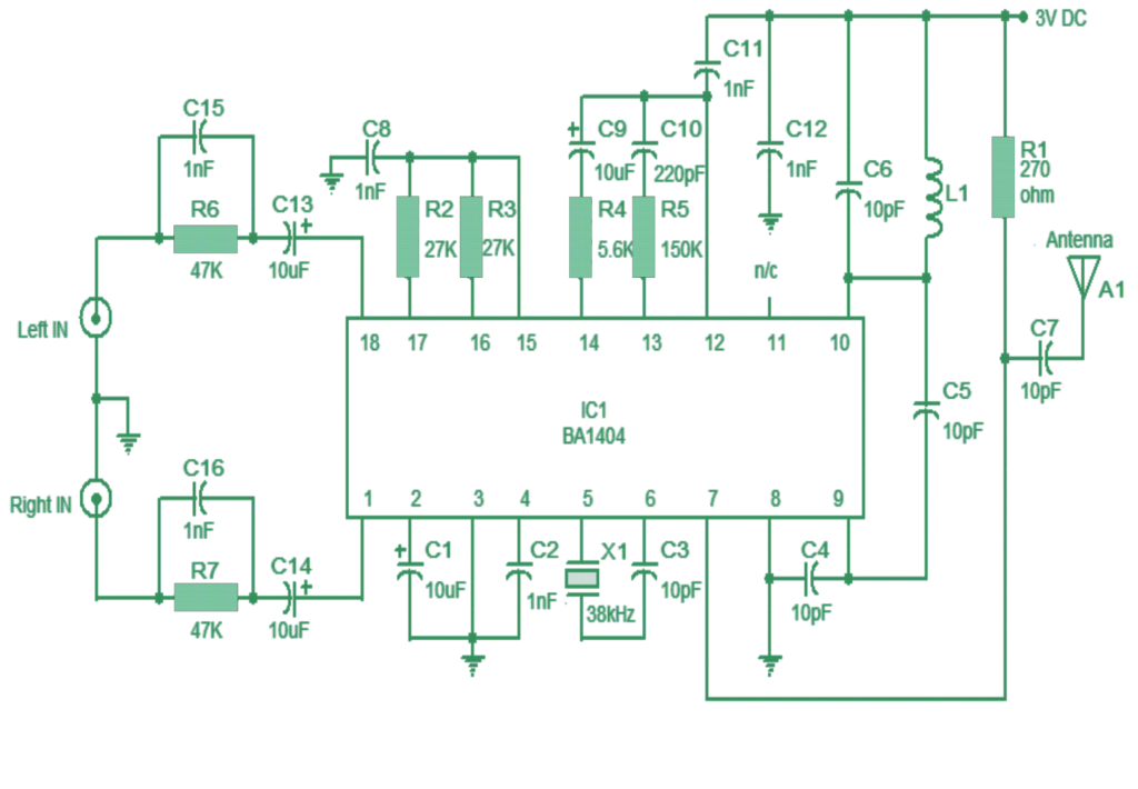
The circuit is in light of the IC BA1404 from ROHM Semiconductors.
BA1404 is a solid FM stereo modulator that has assembled in stereo modulator, FM modulator, RF intensifier circuitries.
How the Circuit Functions
The FM modulator can be worked from 76 to 108MHz and power supply for the circuit can be anything between 1.25 to 3 volts.
In the circuit R7, C16, C14 and R6, C15, C13 frames the preemphasis system for the privilege and left channels individually.
This is finished coordinating the recurrence reaction of the FM transmitter with the FM beneficiary.
Inductor L1 and capacitor C5 is utilized to situated the oscillator recurrence. System C9,C10, R4,R5 enhances the channel detachment.
38kHz gem X1 is joined between pins 5 and 6 of the IC.
Composite stereo sign is made by the stereo modulator circuit utilizing the 38kHz quartz controlled recurrence.
Notes.
Assemble the circuit on a decent quality PCB.
Powering the circuit from a battery will decrease interference.
Utilize a 80 cm copper wire as reception antenna.
For L1 make 3 turns of 0.5 mm dia enameled copper wire on a 5mm diameter ferrite center.
