

A treble booster circuit works extremely well by having an electric guitar (as well as electronic equipment) to enhance the larger order harmonics and present an even more "excellent" sound.
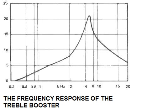
A circuit with this sort provides a relatively flat result at bass and many middle audio frequencies, while using upper middle and lower treble frequencies being provided a large amount of boost.
It really is regular to provide just a simple amount of focus to the upper treble so that you can provide great balance and a low noise level, which furthermore stops the output through sounding too unpleasant.
The frequency reaction of this treble booster circuit is demonstrated within the associated graph.

How the Circuit Works
The treble booster circuit is actually merely an opamp (IC1) utilized in the non inverting amplifier mode. The non inverting input is biased through R4 and R5 by using a decoupling network which is certainly composed of R3 and C3. C4 and C5 provide DC obstructing at the input and output correspondingly.

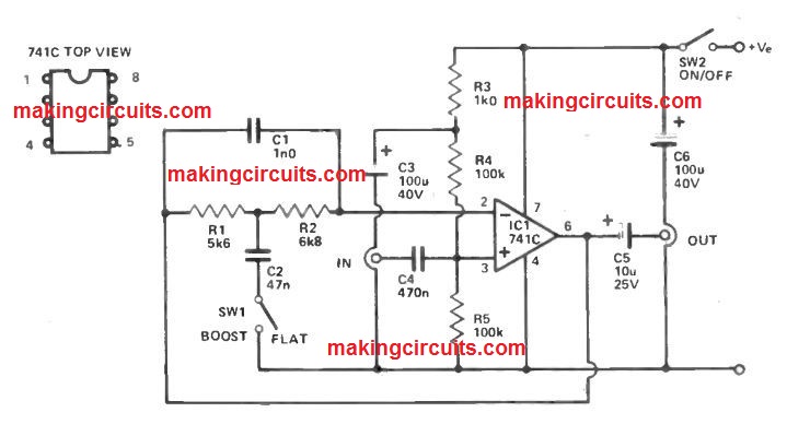
Along with SW1 open there is certainly practically 100% unfavorable feedback via R1, R2 and C1, providing the circuit unity gain and a flat result.
Pressing SW1 delivers C2 into circuit, and this decouples a few of the feedback by means of R1 and R2 at frequencies greater than a few hundred Hz providing the necessary increasing reaction.
Feedback via C1 at high treble frequencies leads to the step to drop away over around 5.5kHz, and inhibits the very higher frequency harmonics through getting extremely emphasized.
Because the unit has unity gain at frequencies where boost is not really used it may just be linked amongst the instrument as well as the amplifier