


The publish points out a very simple compact induction cookware heater circuit or an induction kadai circuit. The design is a low tech, low power design, and might not be comparable to the traditional units.
The recommended induction kadai circuit design in this article is simply for trial/test purpose and might not work such as the standard units. It might be useful for producing a cup of tea or cooking an omelet immediately and that is all ought to be estimated.
The introduced circuit was formerly created for heating iron rod like objects for example a bolt head. a screwdriver metal etc, in spite of this with a number of adjustment the same circuit can be utilised for heating metal pans or vessels with convex base like a "kadai".
For applying the above, the unique circuit would not require any specific alteration, apart from the main functioning coil which can ought to be tweaked a bit to form a flat spiral rather than the spring like arrangement.
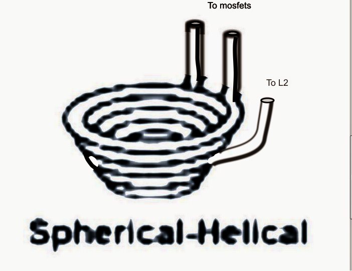
For instance, to be able to transfer the design into an induction cookware to ensure that it facilitates vessels owning a convex bottom for instance a kadai, the coil needs to be constructed into a spherical-helical shape as presented in the figure below:

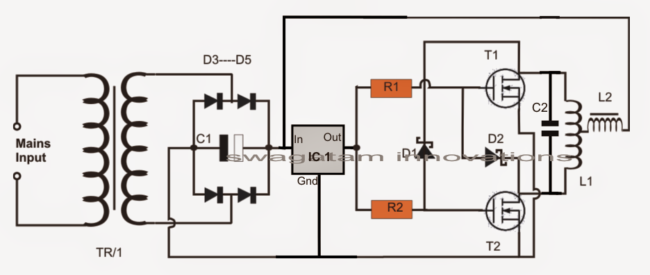
The schematic could be the just like described within my earlier post, that could be essentially a Royer based design, as demonstrated right here:

L1 is created by using 5 to 6 turns of 8mm copper tube into a spherical-helical shape as demonstrated above in an effort to suit a small steel bowl in the middle.
The coil might be as well squeezed flat into a spiral form if a small steel pan is meant to serve as the cookware as presented below:


L2 could very well be constructed by winding a 3mm thick super enameled copper wire over a thick ferrite rod, the number of turns needs to be experimented until a 2mH value is accomplished across its terminals.
TR1 could possibly be a 20V 30amp transformer or an SMPS power supply.
The actual induction heater circuit is pretty simple with its design and will not require much of a clarification, the couple of things that should be looked after are provided below:
The resonance capacitor ought to be comparatively nearer to the main working coil L1 and ought to be created by hooking up around 10nos of 0.22uF/400V in parallel. The capacitors needs to be strictly nonpolar and metalized polyester type.
Even though the design might appear quite simple, choosing the center tap within the spirally wound design might cause some headache simply because a spiral coil might have an unsymmetrical layout which makes it hard to identify the precise center tap for the circuit.
It may be produced by a number of trial and error or by utilizing an LC meter.
A wrongly situated center tap could possibly force the circuit to work abnormally or generating unequal heating of the mosfets, or the whole circuit more than likely are not able to oscillate under a toughest circumstances.
