In this post we will discuss how to build a small weighing scale machine for quickly measuring the weights of small objects or metals, through LED bar graph indications.
Undoubtedly, everyone seems to be informed about the type of scales available on Post Office counters.
A letter or small parcel is positioned onto it and the weight and also the essential postage can be read off it.
There is absolutely no reason why this could not possible be achieved electronically.
Not surprisingly, a few mechanical genius will probably be essential as the equipment includes some type of scale or balance mechanism.
Furthermore, the electronic scales must appear exactly like the mechanical version.
If the latter were not the situation, no body might consider putting a letter on to weight it
Allow us to first think about the electronic specifics.
How the Circuit Works
The very simple circuit is displayed in figure 1. It is made of two ICs and some additional components.

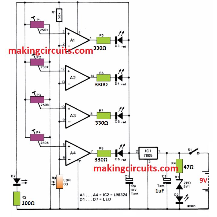
The 9 volt supply from the battery is stabilised by an integrated voltage regulator, 1C1.
Because of this, the registered tariffs are moderately independent of changing voltage supplies (a falling battery voltage).
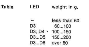
Just like the mechanical model, the electronic scale will certainly show five various rates (see table) through LEDs.

The kind of LED will illuminate based on the weight of the letter positioned on the scales.
The LEDs are turned on by opamps A1 …A4, which can be hooked up as comparators.
Potentiometers P1…P4 are accustomed to set the ' target' voltage at the noninverting inputs of the comparators.
The actual voltage, which is actually a measure of the weight of the letter is fed to the inverting inputs via the light dependent resistor (LDR), R3.
With regards to the level of light extended by the yellow LED, D7, actually falling on the LDR, a specific voltage will be at all four inverting inputs of the comparators.
When this voltage is similar to, or higher than, that preset at the non-inverting input, the relative opamp output will go low.
As the anodes of the LEDs are attached to the positive aide of the power supply, the equivalent LED will illuminate.
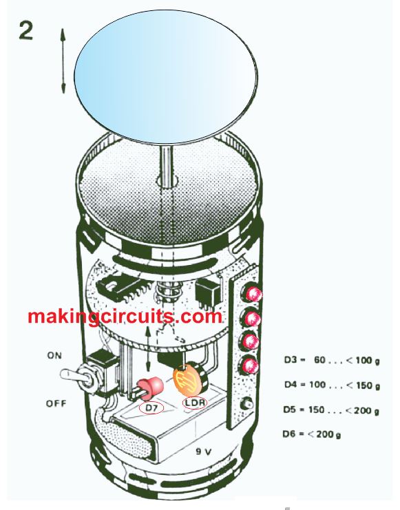
Mechanical Details of the Weighing Scale Body
The mechanical construction of the scales can be seen in the below image

Actually, a very important thing to make use of for this reason is definitely an old beer or soft drinks can.
In fact, two are needed.
The lid of the first one (with the ring-pull) is taken out and thrown away.
The bottom of the second one is also taken out (very carefully) as this will be used as the lid for the first one later on, the remaining of this can can also be disposed of.
A hole that will just permit a ballpoint pen to pass through it is drilled in the bottom of the undiscarded can (which is, actually, applied upside-down).
The ballpoint pen is then attached to the base of the thrown away can.
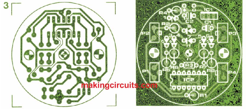
Subsequent, the printed circuit board is installed in the can with adequately long bolts and spacers (see figures 2 and 3).
The precise location of the printed circuit board should be retained in order that the ballpoint pen is put as displayed in the example.
Of course, the pen must be set into place prior to all the bolts are stiffened up.
It should now turn out to be crystal clear the way the LED (D7), the LDR and the point of the pen incorporate to form the opto-coupler.
At this time it is crucial that the LED and/or the LDR be placed precisely.
The ballpoint pen can now be slice to size in order that it just protrudes through the underside of the printed circuit board.
A piece of copper-clad board is then cut to the needed dimensions and glued into the end of the ballpoint.
The subsequent operation is to drill holes in the side of the can to allow the LEDs, the switch (S1) and the holes whereby the preset potentiometers are adjustable.
It is most likely simplest to install the LEDs together on a small piece of Veroboard.
Connections to the main board can then be made via a length of ribbon cable, which, once soldered, can be glued into place.
The 9 V battery can be stuck to the side of the can with a piece of double-sided sticky tape.
Certainly, the positioning of the potentiometer adjustment holes needs to be identified very precisely.
As soon as everything has been packed in and all the soldering completed, the scales are ready for use.
The table displayed right here ought to be mounted on the outside of the can next to the LEDs, in order that the amount of postage needed for the specific letter can be read off right away.
The simple LED weighing scale can be calibrated by modifying the four trimmer potentiometers with identified weights on the scales.
LED D3 should light up over 60 g, D4 over 100 g, D5 over 150 g and D6 over 200 g
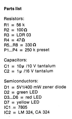
Parts List

PCB Layout