In this article we are going to see how we can make one super simple 50V SMPS symmetric power supply that has no voltage regulation but it can give around 350W power. This thing can directly replace that standard power supply of audio amplifiers. Why? Because it is much cheaper and it is also lightweight. Now, this power supply is working like a half-bridge, but it has no regulation, so it is a plain simple switching supply.
MOSFETs as Power Devices
Now in my power supply we are using two N-channel MOSFETs, and they are driven by an IR2153 IC. That IR2153 IC gets its power through one 27K 6W resistor. So, at full load, we measured the ripple and that is below 2V, which is quite good.
To keep the voltage stable, we are using one 15V Zener diode. Also the frequency is fixed at around 50 kHz, more or less.
Now at the input side, I put one thermistor. Why? Because when the capacitor is charging then it will try to pull a lot of current suddenly so this thermistor will stop that big surge current and protect the system.
This same trick we can find inside those ATX power supplies in computers. Then to keep the leakage inductance low and also to make sure we get full voltage, we first wind 20 turns for the first half of the primary, and then we wind the secondary on top of it.
One important thing! Always connect the output center tap (0V) to the earth. This is for safety, so do not forget it.
Chokes for Filtering RF
Now to remove the high-frequency RF ripple at the output, we are using some chokes. But we do not have to be too serious about how many turns it has or what core is used. We can just pick something from a PC power supply and it will work fine.
Then at the output, I have used some 6k8 resistors. Why? Because when we switch off the power supply, then these resistors will discharge the capacitors so no voltage will remain there. This also stops any unwanted voltage rise when there is no load, then it stays within the safe level.
Now this switching power supply, which is 2x 50V and 350W, is working in a single-switch forward topology. The frequency at which it is working is around 80-90 kHz. It is controlled by the IR2153 IC, which behaves somewhat like the US3842. But in this case, the duty cycle is fixed at 50%, so it is lower than that.
Rewinding an ATX Transformer
For making the transformer Tr1 I simply took one ATX SMPS transformer and rewound it. The primary inductance I measured is around 6.4 mH.
Now in this transformer core, there is no air gap. Also the primary winding is split into two parts: first, we wind half, then we wind the secondary, and after that, we wind the remaining primary turns.
But if we want then we can also use the original primary winding at the bottom without rewinding it. So this power supply is best suited for powering audio amplifiers.
Now if required, then we can also add protection against overload and short circuit. We can even stabilize the output voltage if needed, then we can do that by using feedback with an optocoupler.
Choosing the Right MOSFET
Now when designing for 350W power then we have to take care that when the MOSFET is conducting, then its resistance does not go above 0.8 ohms. Lower is always better. In fact, the smaller the resistance, then the better the efficiency of the whole system.
For voltage handling, we need something that can take between 900V to 1000V. But if nothing else is available then at least 800V should be used in the worst case. After checking, I found that the best MOSFET for this job is SPP17N80C3. If that is not available then we can also use 900V-rated IGBTs.
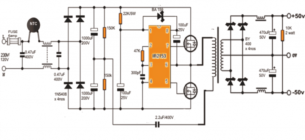
Circuit Diagram
Coil Winding Details:
now here we will see how we have to wind the coils properly for this SMPS transformer. This main transformer which we can see working along with the MOSFETs, has to be wound on one standard ferrite bobbin core that is around 90 mm by 140 mm in square shape.
Primary Winding Details
Now for the primary side winding, we have to take 0.6 mm super enameled copper wire and wind 40 turns. But we do not wind all 40 turns at once. First we wind 20 turns then we stop there. Now we have to take insulation tape and cover this 20-turn winding fully so that it stays safe and does not mix with the next winding.
After this insulation is done, we have to wind the secondary winding on top of it. Once the secondary winding is fully completed, then again we take insulation tape and cover it fully so that it does not touch anything else. After that, we now continue winding the remaining 20 turns of the primary winding over this insulated secondary winding.
So this means the secondary winding gets fully sandwiched between the first 20 turns of the primary and the last 20 turns of the primary. This sandwich structure helps to improve the efficiency of the transformer.
The center tap of this 20 + 20 turns winding, we can connect it with the body of the SMPS. Why? Because this will help to stabilize the output better and make sure there are fewer ripples and buzzing noise at the output side.
Secondary Winding Details
Now for the secondary winding, we have to wind 14 turns but since it is center tapped, we need to make 14 turns × 2 (14 turns on one side and 14 turns on the other side). For this winding also, we have to use 0.6 mm super enameled copper wire.
Filter Coil Winding Details
Now for the input and output filter coils, we have to wind them on ferrite toroidal cores. But here we have to take care that the winding is done in pairs. So the paired winding must be wound together on the same toroidal core.
Again here also, we will use 0.6 mm super enameled copper wire, and we will wind 25 turns on each side of the relevant supply terminals.
So this is how we have to wind the transformer and the filter coils correctly to make sure the SMPS works properly without any interference or disturbances.
| Step No. | Process Description |
|---|---|
| 1 | Take one 90 mm × 140 mm ferrite bobbin core for winding the main SMPS transformer. |
| 2 | For the primary winding, take 0.6 mm super enameled copper wire and wind 20 turns on the core. |
| 3 | Stop winding after 20 turns and apply an insulation layer using insulation tape to separate the next winding. |
| 4 | Now, wind the secondary winding on top of the insulated 20-turn primary. |
| 5 | Once the secondary winding is completed, then apply another layer of insulation tape over it. |
| 6 | Continue winding the remaining 20 turns of the primary winding on top of the insulated secondary. |
| 7 | This winding method ensures that the secondary winding is fully sandwiched between the two halves of the primary winding, improving efficiency. |
| 8 | Connect the center tap of the 20+20 primary winding to the body of the SMPS to reduce ripples and buzzing interference. |
| 9 | For the secondary winding, wind 14 turns × 2 (center tapped) using 0.6 mm super enameled copper wire. |
| 10 | For input and output filter coils, use ferrite toroidal cores. |
| 11 | Wind the paired winding on the same toroidal core using 0.6 mm super enameled copper wire. |
| 12 | Wind 25 turns on each arm of the relevant supply terminals. |
How to Construct the 350 watt SMPS
Step 1 First We Take All Required Parts
So first we take all the parts that we see in the diagram. Ok. We need many things like
- One IR2153 IC
- Two MOSFETs that are N channel high voltage maybe IRF740 IRFP450 or SPP17N80C3
- Four 1N5408 diodes and four BY400 diodes
- One BA159 fast recovery diode
- Many capacitors big and small. Some electrolytic some film. Values we take from the diagram
- Many resistors. Some are high watt types some normal
- A ferrite core. We use for transformer and filter chokes
- One fuse 6A
- One NTC thermistor
- Now once we collect all these then we go to the next step.
Step 2 First We Make the AC Input Section
We take the 230V AC mains and connect it to the input wires.
In one line we put a 6A fuse so that if extra current comes then it breaks and protects everything.
Then we put one NTC thermistor in series to stop big current surge when we first switch on the circuit.
Now we take two 0.47µF 400V capacitors and place them across the AC lines to stop noise.
So this makes the AC input section. Then we move ahead.
Step 3 Now We Build the Rectifier and Filter
We take four 1N5408 diodes and connect them as a bridge rectifier so that AC becomes DC.
Now from this rectifier we get pulsating DC. So we put two big 1000µF 200V capacitors in parallel to filter it and make smooth DC.
So now we have rectified DC voltage which is around 320V DC that we use for switching.
So the power is ready but we cannot use it directly. So we now go to the next step.
Step 4 Now We Make the IR2153 Control Section
First we place the IR2153 IC on the PCB.
Then we give it power using a 22K 5W resistor in series.
We put one 100µF 25V capacitor to smooth its power.
Then we add two 150K resistors for setting the oscillation frequency of the IC.
Next we put one 47K resistor and one 300pF capacitor to fine-tune the IC timing.
We also take one BA159 diode and connect it to the circuit so that the IC gets protection from reverse voltage.
Finally we add one 2.2µF 400V capacitor for further stabilization.
Now the IC section is ready. So next we connect the MOSFETs.
Step 5 Now We Place the MOSFETs for Switching
We take two MOSFETs and fix them on the board.
We connect their gate terminals to IR2153 output pins as per the diagram.
The source terminals we connect to the ground.
We also take big heat sinks and attach them to MOSFETs so that they do not heat up too much.
So now the switching section is ready. But still there is no real power output. So we need a transformer.
Step 6 Now We Wind the Transformer
First we take one 90mm × 140mm ferrite core bobbin.
Now for the primary winding we take 0.6mm enameled copper wire and wind 40 turns.
First we wind 20 turns then we stop. Then we put insulation tape over it.
Then we take the secondary winding and wind it over the tape.
After that we again put insulation tape and then we complete the remaining 20 turns of the primary winding.
This method makes the secondary winding sandwiched between the primary 20 plus 20 turns.
The center tap of this 20 plus 20 primary we connect to the body of the SMPS to reduce noise.
For the secondary winding we take 0.6mm enameled wire and wind 14 turns times 2 with center tap in the middle.
Now the transformer is ready. So we go ahead.
Step 7 Now We Make the Output Rectifier and Filter
We take four BY400 diodes and arrange them as a full-wave rectifier.
We take two 470µF 50V electrolytic capacitors and put them across the output for filtering.
Then we take one 10K 2W resistor and put it across the output to discharge the capacitors safely when the circuit is OFF.
Now we get plus 50V 0V minus 50V DC output.
So the power supply is almost ready. But still we need filtering to remove unwanted signals.
Step 8 Now We Wind and Install the Output Filter Chokes
We take ferrite toroidal cores for making filter chokes.
We take 0.6mm enameled copper wire and wind 25 turns on one side of the toroid.
Then we wind 25 turns on the other side.
We connect these chokes in series with the output rails so that high-frequency noise is reduced.
Now we come to the final step.
Step 9 Now We Test Everything
First we check all connections one by one to make sure nothing is shorted.
We take a multimeter and measure the resistance between different points to confirm there is no short circuit.
We take a variable AC source and slowly increase the input voltage.
We check the DC output voltages plus 50V minus 50V to see if everything is working.
We connect a small load and observe if the circuit is stable.
If we see too much heating then we check heat sinks and MOSFETs.
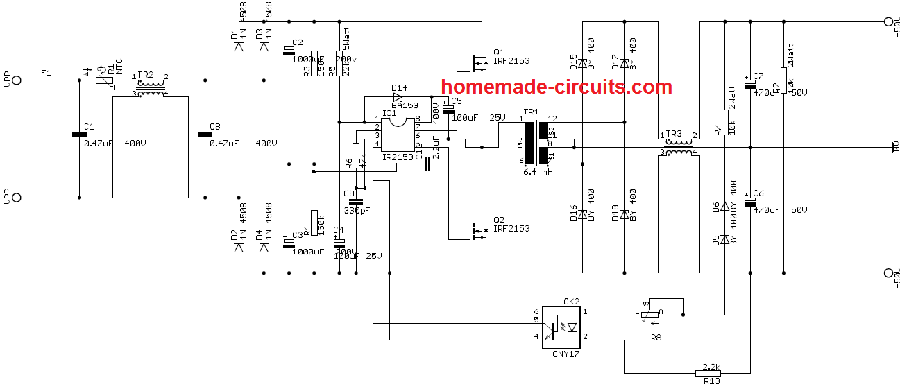
Update:
The above design 350 watt SMPS circuit can be further improved by adding an opto-coupler based feedback voltage controller stage, as shown in the following diagram.