

The following article provides an explanation of a straightforward solar inverter circuit designed specifically for beginners or school students who are just starting out in this field.
In this setup the battery is directly connected to the solar panel to keep things simple. Additionally, there is an automatic changeover relay system that switches the battery to the inverter when there is no solar energy available.
This circuit design was requested by Ms. Anna David.
Stages of the Circuit
The circuit primarily consists of two main stages which are a basic inverter and the automatic relay changeover system.
During daylight hours when sunlight is sufficiently strong, the voltage generated by the solar panel is utilized to charge the battery while also powering the inverter through the contacts of the relay changeover system.
The preset configuration of the automatic changeover circuit is designed so that the associated relay will turn off when the voltage from the solar panel drops below 13 volts.
This action effectively disconnects the solar panel from the inverter and connects the charged battery to the inverter, ensuring that any connected output loads continue to operate using power from the battery.

Circuit Operation
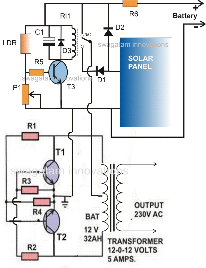
In this particular circuit we have a combination of resistors labeled R1 R2 R3 and R4 along with transistors T1 and T2 as well as a transformer which together create the inverter section.
When we apply twelve volts across the center tap and the ground the inverter springs into action right away. However it is important to note that we do not connect the battery directly at these specific points. Instead we utilize a relay changeover stage to facilitate this connection.
The transistor T3 along with its associated components and the relay works together to form the relay changeover stage. An LDR or light dependent resistor is positioned outside of the house or in a location where it can effectively detect daylight.
The P1 preset is carefully adjusted so that T3 will just stop conducting when the ambient light dips below a certain threshold. This can also occur when the voltage falls below thirteen volts.
This scenario typically takes place when sunlight becomes too weak to maintain the required voltage levels. Nevertheless as long as there is bright sunlight available the relay remains activated.
This allows for the solar panel voltage to be connected directly to the inverter through the normally open contacts of the relay. Consequently during daylight hours the inverter can be utilized effectively through the solar panel.
Additionally during the daytime the solar panel is also employed to charge the battery via diode D2. This ensures that by the time dusk arrives the battery is fully charged and ready for use.
It is worth mentioning that the solar panel is specifically chosen so that it will never produce more than fifteen volts even under peak sunlight conditions. The maximum power output from this inverter will not exceed sixty watts.
Parts List for Proposed Solar Inverter with Charger Circuit Intended for Science Projects
| Component | Specifications |
|---|---|
| R1, R2 | 100 Ohms, 5 Watts |
| R3, R4 | 15 Ohms, 5 Watts |
| T1, T2 | 2N3055, Mounted on suitable heatsink |
| Transformer | 9-0-9V, 3 to 10 Amps |
| R5 | 10K |
| R6 | 0.1 Ohms, 1 Watt |
| P1 | 100K Preset Linear |
| D1, D2 | 6A4 |
| D3 | 1N4148 |
| T3 | BC547 |
| C1 | 100uF/25V |
| Relay | 9V, SPDT |
| LDR | Any standard type |
| Solar Panel | 17 Volts open circuit, 5 Amps short circuit current |
| Battery | 12 V, 25 Ah |