


The circuit and the mechanism described in this post might be regarded as the simplest and ideal dual axis solar tracker system.
The device has the capacity to track the daytime motion of the sun accurately and move in the vertical axis appropriately.
The device also efficiently monitors the seasonal displacement of the sun and moves the whole mechanism in the horizontal plane or in a lateral motion such that the orientation of the solar panel is actually saved in a right axis to the sun so that it enhances the vertical actions of the tracker accordingly.

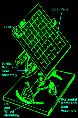
solar tracker mechanism with gears and dimensions
As demonstrated in the figure, a comparatively simple mechanism may be observed right here. The solar tracker is essentially installed over a few stand with a central movable axis.
The pivotal arrangement permits the panel mounts to proceed a circular axis over nearly 360 degrees.
A motor gear mechanism as presented in the diagram is installed just at the corner of the pivotal axis in such a means that when the motor revolves the total solar panel changes correspondingly regarding its central pivot, either anticlockwise or clockwise, based upon the motion of the motor which often is dependent upon the position of the sun.
The place of the LDRs are important listed here and the set of LDR which symbolize this vertical plane motion is so placed that it experiences the sun light precisely and attempts to keep the panel perpendicular to the sun rays by moving the motor in the suitable direction by means of an obvious variety of stepped rotations.
The LDR sensing is really precisely obtained and interpreted by an electronic circuit which orders the motor for the above discussed measures.
An additional mechanism which can be quite much like the above vertical setting, but moves the panel by means of a lateral motion or rather it moves the whole solar panel mount in circular motion over the horizontal plane.
This movement occurs as a reaction to the situation of the sun throughout the periodic changes, consequently as opposed to the vertical activities; this operation is extremely constant and simply cannot be experienced each and every day.
Once more the above motion is in reaction to the command provided to the motor by the electronic circuit which functions as a reaction to the sensing produced by the LDRs.
For the above process a different set of LDRs are utilized and are fitted horizontally over the panel, at a particular position as demonstrated in the diagram.
How the Solar Tracker Control Circuit Performs


A cautious research of the circuit demonstrated in the diagram shows that the entire design is definitely quite simple and simple. Right here a single IC 324 is commonly employed and only two of its op amps are being used for the preferred procedures.
dual axis solar tracker LDR circuit
The op amps are primarily cabled to form a type of window comparator, to blame for signaling their outputs at any time their inputs waver or drift out of the fixed window, set by the appropriate pots.
Two LDRs are linked to the inputs of the opamps for sensing the light levels.
Provided that as the lights over the two LDRs are even, the outputs of the opamp stay deactivated.
In spite of this the moment one of the LDRs detects an unique magnitude of light over it (which can take place as a result of the altering position of the sun) the balance over the input of the opamp shift toward one direction, instantly producing the pertinent opamps output go high.
This high output immediately triggers the full bridge transistor network, which often spins the linked motor in a set direction, such that the panel revolves and adjusts its alignment with the sun rays until uniform amount of light is renewed over the relevant set of LDRs.
As soon as the light level over the relevant LDR sets is gained, the opamps again turn out to be inactive and switch off their outputs as well as the motor.
The above series retains on occurring for the complete day, in steps, as the sun alters its posture and the above mechanism maintains moving in respect to the suns position.
It ought to be mentioned that two sets of the above described circuit assemblies is going to be essential to managing the dual measures or simply just to create the above mentioned dual tracker solar system mechanism.
Parts List
R3 = 15K,
R4 = 39K,
P1 = 100K,
P2 = 22K,
LDR = Normal type with a resistance of around 10 K to 40K in daylight under shade and unlimited strength in total darkness.
Op-amps are from IC 324 or separately two 741 ICs can also be incorporated.
T1, T3 = TIP31C,
T2,T4 = TIP32C,
All diodes are 1N4007
Motor = As per the load and size of the solar panel
Courtesy - Elector Electroniks India
Tips on how to Add a Set/Reset Facility in the Above Circuit
At the initial look it may seem that the above circuit is not going to incorporate an automatic resetting feature. Nevertheless a closer study indicates that really this circuit will reset instantly when dawn sets in or in the morning daylight.
Perhaps this is correct simply because that the LDRs are located inside enclosures that happen to be specfiially created in a "V" shape for helping this activity.
From the reflection of of the rising sun light, in the course of morning hours the sky gets more activated than the ground. Since the LDRs are placed in "V" manner, the LDR which encounters more toward the sky obtains more light than the LDR which faces toward the ground. This scenario stimulates the motor in the opposite direction, such that it causes the panel to revert at the start of morning hours.
As the panel reverts in the direction of the east, the relevant LDR starts obtaining subjected to all the more ambient light from the rising sunlight, this transmits the panel even harder toward the east until both LDR are practically consequently uncovered toward the east rising sunlight, this totally resets the panel to ensure that the method commences once again.
![]()

solar tracker system information with LDR installation and gear fitting
Set Reset Function
In the event a set reset characteristic turns into crucial, the following design could be integrated.
The set switch is put at the "sun-set" end of the tracker, such that it becomes desperate when the panel finishes it's days tracking.
As can be viewed in the below given figure, the supply to the tracker circuit is been given from the N/C points of the DPDT relay, it implies when the 'SET" switch is pressed, the relay triggers and disconnects the supply to the circuit so that the whole circuit proven in the above post now gets turned off and fails to interfere.
Simultaneously, the motor draws the reversing voltage via the N/O contacts so that it can start the reversing strategy of the panel to its original position.
Once the panel finishes its reversing method toward the "sun-rise" end, it forces the reset switch positioned suitably somewhere at that end, this steps deactivates the deliver yet again resetting the total system for the next cycle.
![]()
