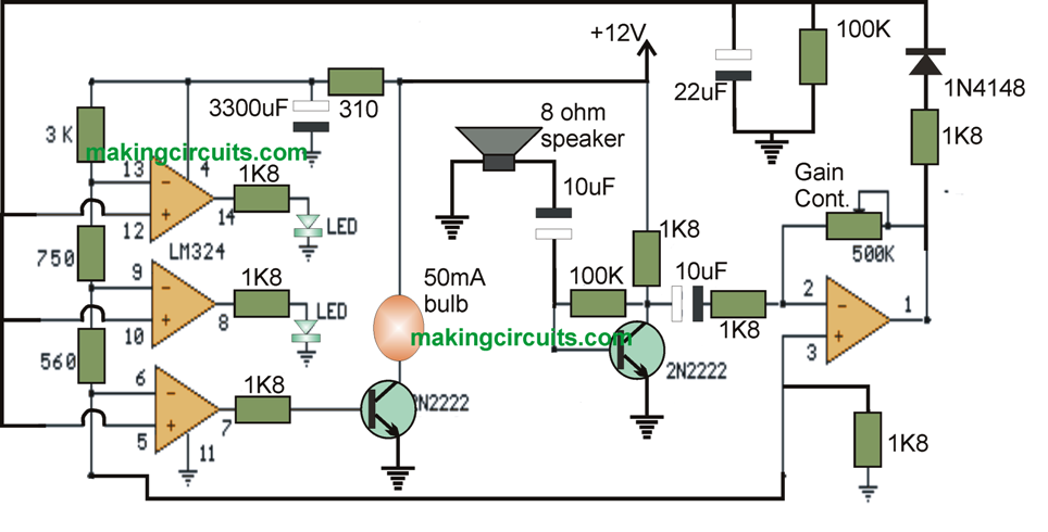
The sound decibel meter circuit shown underneath reacts to audio air pressure concentrations from approximately 60 to 70 dB. The sound is sensed by an eight ohm loudspeaker, intensified by a transistor stage together with a LM324 op-amp stage.
The other three segments of the LM324 quad op-amp are being used as voltage comparators in order to operate three warning LEDs or incandescents lamps spaced roughly 3dB from each other.
Additionally you can make use of an active microphone yet somehow it appears that the loudspeaker was considerably more receptive.
A supplementary transistor works good for incandescent light bulbs as demonstrated with the lower light bulb. I accustomed 12 volt, 50mA light bulbs.
Each individual light bulb symbolizes approximately a 3dB difference in audio intensity making sure that each time all three lamps are on, the sound intensity comes to four times exceeding the intensity aloted to illuminate just one light bulb.
The level of responsiveness are typically conditioned with the 500K pot making sure that a single light bulb switches on with a reference sound intensity.
The supplementary pair of light bulbs could very well signal roughly a 2X and 4X improvement in volume level.
When running, without any input, the DC voltage at pins 1,2 and 3 of the op-amp are likely to be approximately four volts, while the voltage on the (+) inputs to the three comparators (pins 5,10,12) will probably be roughly a one half volt lower on account of the 1N914 diode reduction.
The voltage on the (-) comparator inputs is going to be around 5.1 and 6.5 that may be fixed by the 560 and 750 ohm resistors.
Given that the volume level goes up, the DC voltage on the capacitor including (+) comparator inputs skyrockets making the light bulb switch on each time the (+) input gets above the (-) input.
The minute an sound reception is found, the 10uF capacitor hooked up to the diode is going to charge in the direction of the optimum sound intensity at the op-amp output at pin 1.
Once the sound subdues, the capacitor discharges by means of the matching 100K resistor causing the light bulbs shut off. It is possible to switch the impulse time period with a more substantial or scaled-down capacitor.
This sound decibel meter circuit necessitates a nicely cleaned power supply, it will no doubt be affected by diminutive fluctuations in supply voltage, which means you would most likely have to have a sizable filter capacitor hooked straight to the 330 ohm resistor. I got it to accommodate an unregulated wall transformer power supply, however I needed to implement 4700uF. It proved helpful on a controlled supply having only a solitary 1000uF.