

More often we need to switch an electric light or an electronic apparatus from various parts from the same building. A particular instance for this is hotel where this switch allows us to control lights from different positions of a hotel. With the addition of some electronics and electric wiring the number of switching position may be increased as infinium.

Circuit Description
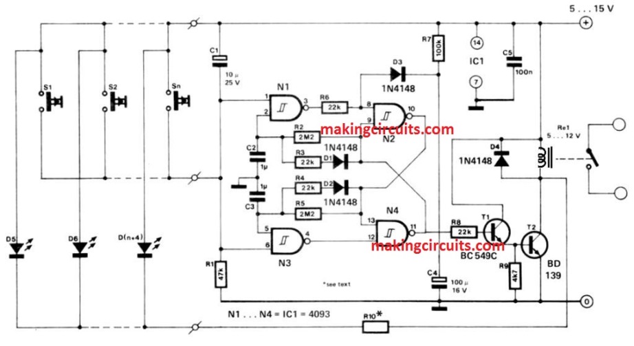
However, the actual switching of the lights is controlled by a relay. This relay is again controlled by an R-S bi-stable, N2/N4 via the transistor designated as T1 and T2. The logic switches are N1 and N3. The state of the bi-stable is of import to the position of logic switches.
A trigger pulse is being applied at the junction of R1 and C1 – this trigger pulse makes the bi-stable toggle. This means, a train of trigger pulses of 0, 1,0,1,0 with a minimum interval between pulses of a few seconds - as a result of which a series of logic level changes. This change causes the relay to be alternatively actuated and lose energy.
When one of the push buttons, S1 …to Sn is being pushed, the trigger pulses arise. The push buttons are all connected in parallel - this enables them to stay interlinked by a two-wire system.
It is possible to fit an LED at every ON/OFF switch point. However, this will require an additional wire. Such LEDs have to necessarily be in parallel. That is why it is advised to use similar types.
The value of resistor R10 is obtained from R10= ((U-2)/ I Dn) Ω ; here U refers to the supply voltage expressed in volts; ID is the current passing through every LED in A and n refers to the numbers of LEDs.