The post explains a simple yet very useful touch operated flip flop circuit. It operates by touching a sensor pad which results in an alternate high/low logic outputs in response to alternate touch contacts. Meaning the output of the circuit will turn ON/OFF alternately in response to touching of the input touch sensor pad.
All circuits for Touch Activated Program switches published till now were described worked with two pairs of touch contacts. The first was to set the touch flip flop “on” and the other was to reset it back to off.
How it Works
The circuit described here is unique in that it has only one touch contact that can be touched for the first time to set the and another time to reset it.


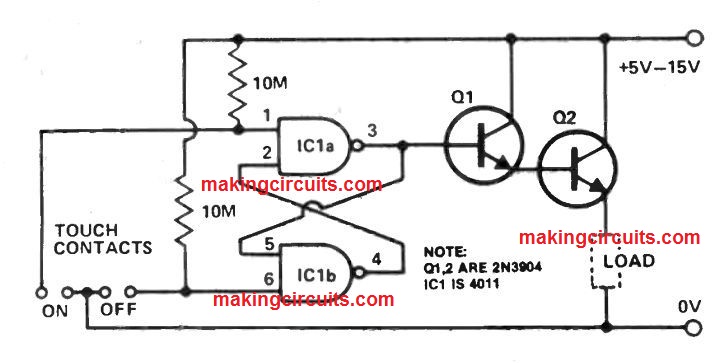
A bistable multivibrator or flip-flop is created by N1 and N2. The output of N2 is assumed to be low initially.
As the inputs of N1 is set to low by R1, its output would be high. This causes a high input for N2, resulting in a low output for it, according to our assumption.
The high output of N1 charges C1 to logic high via R3. When the touch contacts are touched, the input of N1 will receive the logic high on C1 via R1 and the resistance of the bridging skin.
This will make the output of N1 low and thus, that of N2 high, so that the input of N1 will now be held at high even after the removal of the finger. This sets the TAP.
After the removal of the finger, C1 starts discharging through R3 to the low output of N1. If you touch the touch contacts again, the discharged C1 will bring the inputs of N1 down, thus making its output high and that of N2 low.
This will hold the inputs of N1 at low even after the bridging by the finger is removed, thus resetting the TAP. C1 will also be charged back to logic high by the high output of N1 via R3.
This touch sensitive ON/OFF circuit has a mild drawback, which is that the touch contacts cannot be touched within half a second of the previous touch or C1 will not get enough time to charge and discharge.
How to Connect a Relay
If you want to connect a relay at the output of this touch flip flop, you can simply do it by integrating a transistor relay driver stage with the output of the gate N2.
Low Current Touch Switch Circuit
The expense of several CMOS ICs is currently less than a mechanical on /off switch.
Making use of just one half of a 4011, along with a a number of standard purpose transistors, a low current touch operated switch circuit could be built which can be well suited for numerous battery powered circuits.

Hoping the fact that inputs to the rest of the 4011 are rendered low, the current pulled in the off condition is nearly minimal and battery life is barely impacted.
When the 'on' contacts are touched using a finger provides pin 3 high, turning on the darlington pair and providing power to the load (transistor radio etc).
For this low current touch switch circuit Q1 must be a high gain transistor, and Q2 selected for the current needed by the load circuit.
Improved SPST Switch Flip -Flop Circuit
This SPST switch flip -flop circuit provides the benefit it could be driven by an input referenced to earth logic outputs or push buttons.

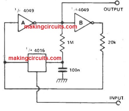
When the 4016 input moves high it links jointly the input to A and C. This 'flips' the latch.
The 20k resistor relating to the output of invertor B and the input of A is required as the 4016 are unable to draw the output of inverter B down instantly.
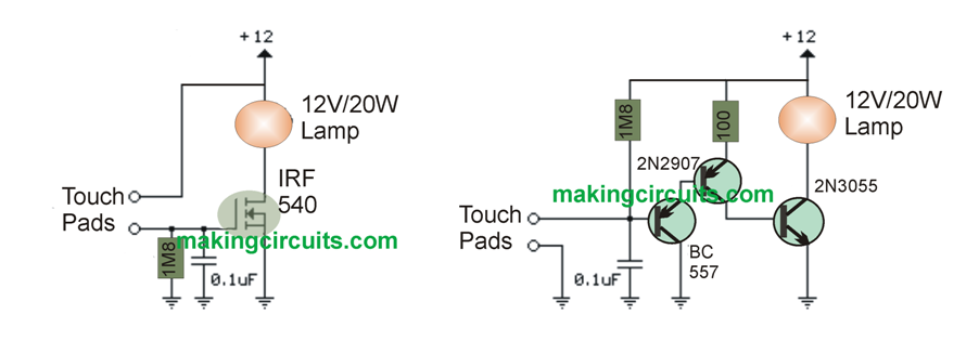
Simple Touch Sensitive Switch Circuit without Flip Flop
The two simple touch sensitive switch circuits listed below illuminate a 20 watt light bulb any time the connections are confronted so the skin resistance is mostly about a couple of Megs or lesser.
The circuit on the left hand side makes use of a power MOSFET which switches on every time the voltage in between the supply and gate is approximately 6 volts.
The gate of the MOSFET consumes zero current as a result the voltage on the gate is going to be fifty percent the supply voltage or six volts whenever the level of resistance around the touch leads is on par with the set resistance (2 Megs) in between the supply and mosfet gate.
The simple touch sensitive switch circuit on the right hand side takes advantage of 3 BJT to fulfill the equivalent outcome by using the touch approach referenced to the negative or ground ending of the source.
Because the base of a BJT consumes current as well as the current gain is invariably below 200, several transistors combine to elevate the uamp current intensity by way of the touch contacts to a good number of amps essential to the illumination.
For extra current, the light bulb could possibly be swapped with a 12 volt relay and diode parallel with the coil.