


This, certainly one of its kind and difficult to find triac control AC voltage stabilizer circuit has been created in particular simply for you. Being solid state in design, the voltage switching transitions are extremely smooth with minimum damage, leading to beneficial voltage stabilization. Find out the entire development technique of this excellent, solid state mains voltage stabilizer.
The suggested circuit of a triac controlled AC voltage stabilizer will give you an outstanding 4 step voltage stabilization to any appliance at its output. With no moving parts involved its effectiveness is even more improved. Understand more of this silent operator: power guard.
Introduction
The circuit of an automatic voltage stabilizer mentioned in one of my earlier content, though useful, as a result of its less complicated design, is lacking in the ability of regulating the various levels of varying mains voltages discretely. The suggested concept though not tested, appears quite convincing, and if the crucial parts are correctly dimensioned, should perform naturally.
The existing circuit of triac controlled AC voltage stabilizer is excellent in its efficiency and is pretty much the best voltage stabilizer in every respect. As normal the circuit continues to be exclusively manufactured by me. It is going to manage and dimension the input AC mains voltage precisely by means of 4 independent measures.
The utilization of triacs ensure it is sure that the changeovers are fast (within 2 mS) and with no sparks or transients generally connected with relay type of stabilizers. Also since no moving parts are being used, the complete unit turns into totally solid state and almost long lasting.
Let’s proceed to notice precisely how the circuit features.
Extreme caution: Every Single Purpose OF THE CIRCUIT In This Article Might Be AT AC MAINS POTENTIAL, For that reason EXTEMELY Harmful TO TOUCH IN Turned On POSITION. UTMOST Attention AND Care IS Recommended, Utilization Of A WOODEN PLANCK UNDER YOUR FEET Is Advisable. Beginners PLEASE Avoid.
Circuit Explanation
The operating of the circuit might be recognized by means of the following points:
Transistors T1 to T4 are all organized to sense the constant rise in the input voltage and perform one after the other in series as the voltage goes up and vice versa.
Gates N1 to N4 from IC 4093 are set up as buffers. The outputs from the transistors are given to the inputs of these gates.
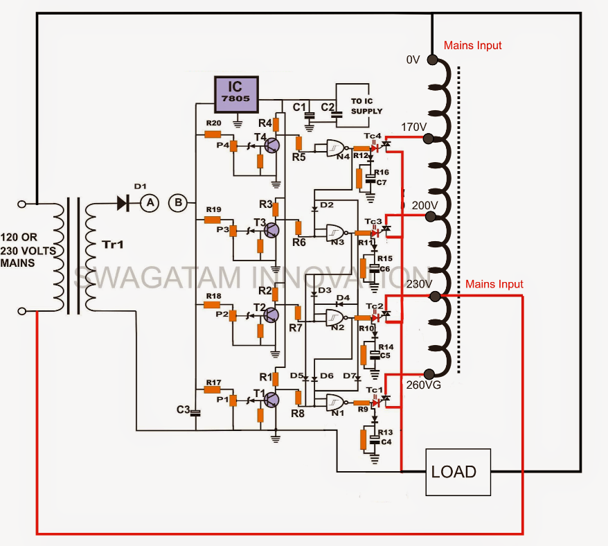

All the gates are correlated to one another in such away that the output of only a specific gate remains effective at a particular time frame in accordance with the level of the input voltage.
Thus, as the input voltage increases the gates react to the transistors and their outputs eventually turn out to be logic hi one after the other making certain that the earlier gate’s output is shut OFF and vice versa.
The logic hi from the particular buffer is used on the gate of the specific SCR which performs and attaches the appropriate “hot” line from the transformer to the external associated appliance.
As the voltage increases, the appropriate triacs eventually choose the suitable “hot” ends of the transformer to raise or reduce the voltage and preserve a somewhat maintained output.
Construction Clues and Testing Tips
The construction of this triac control AC power guard circuit is easy and just couple of picking out the needed parts and assembling them properly over a basic PCB. It is pretty obvious that the individual who is trying to make this circuit knows a little more than simply the fundamentals of electronics. Points might go absolutely wrong if you experience any mistake in the final set up.
You prefer an external variable (0 to 12 volts) universal DC power supply for setting up the unit in the following way:
Provided that an output supply of 12 volts from TR1 symbolize to 225 volts input supply, by means of calculations we come across that it will generate 9 volts at an input of 170 volts, 13 volts will correspond to 245 volts and 14 volts will be comparable to an input of around 260 volts.
In the beginning keep the points “AB” turned off and make sure the circuit is completely turned off from the AC mains.
Change the external universal power supply to 12 volts and hook up its positive to the point “B” and negative to the common ground of the circuit.
Now adjust P2 until LD2 is just turned on. Reduce the voltage to 9 and adjust P1 to turn on LD1.
Likewise, adjust P3 and P4 to light up the appropriate LEDs at voltages 13 and 14 respectively.
The setting process is now finish. Remove the external supply and join points “AB” together.
The entire unit may now be attached to the mains AC so that it can begin working immediately.
You might confirm the efficiency of the system by providing a varying input AC by means of an auto transformer and consulting the output utilizing a digital multimeter.
This triac controlled AC voltage stabilizer will shut OFF at voltages below 170 and above 300 volts.
Parts List
You prefer the following parts for the development of this SCR control ac voltage stabilizer:
All resistors are ¼ Watt, CFR 5%, unless otherwise stated.
R5, R6, R7, R8 = 1M ¼ watt,
All Triacs are 400 volts, 1KV rated,
T1, T2, T3, T4 = BC 547,
All zener diodes are = 3 volts 400 mW,
All Diodes are = 1N4007,
All presets = 10K linear,
R1, 2, 3, 4, 9, 10, 11, 12, 13, 14, 15, 16, 17, 18, 19, 20 = 1K ¼ watt,
N1 to N4 = IC 4093,
C1 and C3 = 100Uf/ 25 volts,
C2 = 104, ceramic,
Power Guard Stabilizer Transformer = “Made to order” having 170, 225, 240, 260 volts output Taps at 225 volts input supply, or 85, 115, 120, 130 volts taps at 110 AC input supply.
TR1 = Step down transformer, 0 - 12 volts, 100 mA.