

Now we talk about one idea which is that two tone alarm generator using frequency modulation method through IC 4011 NAND gates.
So in this new concept we are going to use a type of modulating system where we make the output tone frequency go up and down in a planned way using the IC 4011.
Now this thing is already known and people have used this idea before and it works really nicely for making interesting alarm sounds.
So here how it works is that we are going to modulate the main tone with a second oscillator.
What happens when we use a square wave as modulating signal
If we use a square wave signal for modulation then we will see that the tone at the output starts changing suddenly between two fixed tones.
So like one moment the tone will be one frequency and next moment it will jump to another tone.
This jump happens back and forth and the speed of this switching depends on how fast that modulating square wave is oscillating.
If that modulation oscillator is running fast then we get fast tone switching and if it is slow then we get slow tone switching.
What happens when we use triangle wave for modulation
But now if we try a triangle wave instead of square wave as modulation input then something different happens.
Here the output tone does not jump like before but it changes slowly and linearly.
So when the triangle wave rises then the tone slowly increases and when triangle wave falls then the tone also slowly decreases.
So we get this type of siren like sound where the tone keeps rising and falling in a smooth way.
This gives a very effective alarm effect which sounds serious and attention catching.
How both oscillators are linked and how the effect is created.
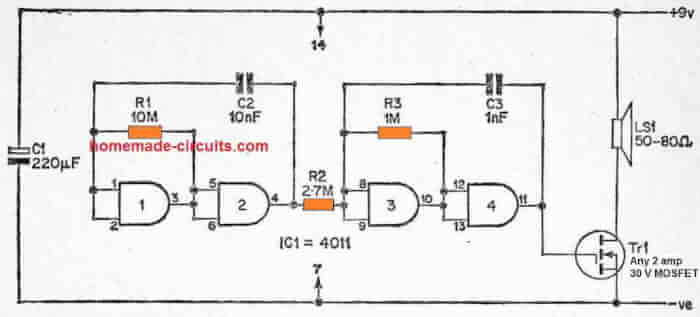
We have one oscillator using two NAND gates which is working like a modulator and another oscillator using other two NAND gates which is making the actual tone.
These two are connected together in such a way that the modulator output is weakly connected to the input of the tone generator.
So this weak connection is just enough to influence the tone oscillator and push its frequency up and down.
Now whenever the modulating oscillator changes its logic state then the frequency of tone generator also shifts.
Because of this thing the tone generator does not work at its normal fixed frequency anymore.
Final result at the output
So now instead of one single tone we get a back and forth changing tone.
In the example setup which we are talking about, the tone is not fixed but it keeps going between around 500 Hertz and 1.2 kHz.
This tone variation makes the alarm much more interesting and attention grabbing compared to single tone sound.
So that is how this simple two tone alarm generator works using frequency modulation method.

Construction Steps for the Above Two Tone Alarm Generator Circuit
1) Collect All the Parts First
So before we start soldering or wiring anything, we must first collect all the important parts:
- IC 4011 – CMOS NAND gate IC (we use all 4 gates).
- Resistors – 10M, 2.7M, 1M (1/4 watt, 5% ok).
- Capacitors – 10nF (x2), 1nF (x1), 220µF/25V (x1).
- Speaker – 8 ohm to 50 ohm small speaker or buzzer.
- MOSFET – any N-channel type that can handle 2 amps and 30V (like IRFZ44N or IRF540N).
- Power – 9V battery or DC adapter.
- Some wires and general purpose PCB or breadboard.
- Soldering kit if needed.
2) Prepare the IC 4011 Setup
Now we take our IC 4011 and carefully put it on the breadboard or PCB. This IC has 14 pins. Make sure pin 7 goes to negative (ground) and pin 14 goes to positive (9V).
We will use all 4 NAND gates inside the IC:
- Gate 1: pins 1, 2 in, pin 3 out.
- Gate 2: pins 5, 6 in, pin 4 out.
- Gate 3: pins 8, 9 in, pin 10 out.
- Gate 4: pins 12, 13 in, pin 11 out.
3) Make the Modulator Section (First Oscillator)
Now we make the oscillator using Gate 1 and Gate 2. This will work like the modulating signal generator, probably a square wave type.
- Connect 10M resistor between pins 1 and 2.
- Connect 10nF capacitor from pin 2 to negative (ground).
- Join pin 3 to pins 5 and 6 of Gate 2.
- Connect pin 4 back to pin 1 using a wire.
- This makes one square wave oscillator.
4) Build the Tone Generator Oscillator
Now we move to the next oscillator using Gate 3 and Gate 4. This part will generate the actual alarm tone that we hear from the speaker.
- Connect 1M resistor between pins 8 and 9.
- Connect 1nF capacitor from pin 9 to ground.
- Connect output pin 10 to inputs pins 12 and 13.
- Pin 11 is the final output that goes to the MOSFET.
5) Connect Both Oscillators Together
We want our modulator to control the frequency of the tone oscillator. For that we connect them like this:
- Take a 2.7M resistor and join it between pin 4 (modulator output) and pin 9 (tone input).
This weak connection lets the first oscillator affect the second one.
So whenever pin 4 output changes from high to low, the tone frequency also jumps a bit.
This makes the output tone keep swinging between 500 Hz and 1.2 kHz.
6) Connect Output Stage using MOSFET
Now we take the output from pin 11 and use it to drive a small speaker.
Since the IC cannot drive a speaker directly, we use a small MOSFET amplifier stage.
- Connect pin 11 to gate of MOSFET (Tr1).
- Connect source of MOSFET to ground.
- Connect drain of MOSFET to one end of speaker.
- Connect the other end of speaker to positive 9V.
This way the MOSFET acts like a switch and passes the oscillations to the speaker.
7) Add Power Supply
- Connect 9V battery or DC supply.
- Positive goes to pin 14 of IC and speaker.
- Negative goes to pin 7 and other ground points.
Also place a 220uF capacitor across power lines to prevent voltage spikes.
8) Testing the Circuit
Once everything is connected:
- Switch ON the power.
- You will hear a strange alarm sound from the speaker.
- The tone will keep changing between low and high.
- If not working, check all connections and component values.
9) Mount and Finalize the Circuit
Once your testing is done, mount everything on a PCB or a plastic box.
Keep IC protected from dust and moisture.
You can also use a small amplifier stage if volume is low.
Parts List for Two-Tone Alarm Generator Circuit Using IC 4011
| Part Name | Value / Type | Quantity | Description / Notes |
|---|---|---|---|
| IC1 | 4011 (Quad 2-input NAND gate) | 1 | Main logic IC used for oscillators |
| R1 | 10 Mega ohms (10M) | 1 | Resistor for modulating oscillator |
| R2 | 2.7 Mega ohms (2.7M) | 1 | Connects modulator to tone oscillator |
| R3 | 1 Mega ohm (1M) | 1 | Resistor for tone oscillator |
| C1 | 220µF / 25V | 1 | Power supply filter capacitor |
| C2 | 10nF | 1 | Capacitor for modulator oscillator |
| C3 | 10nF | 1 | Same as C2 (or can be combined with it) |
| C4 | 1nF | 1 | Capacitor for tone generator oscillator |
| Speaker (LS1) | 50Ω to 80Ω | 1 | Output buzzer or speaker |
| Tr1 (MOSFET) | Any N-channel, 2A, 30V min | 1 | Example: IRF540N, IRFZ44N, 2N7000 etc. |
| Battery / Power Supply | 9V DC | 1 | Battery clip or DC jack |
| General PCB or Breadboard | – | 1 | For assembling the circuit |
| Wires / Jumpers | – | As needed | For making connections |
| Solder + Iron (optional) | – | As needed | Only if you're assembling on PCB |