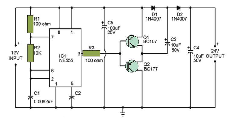
The following circuit diagram below illustrates a voltage doubler. Here, it uses IC NE555, running on 9KHz (approx.) and working as astable multi-vibrator. The Q1 and Q2 as the transistors base gets shorting and Pin 3 if further connected to it. Now, when the multi-vibrators remain low, the impact is on Q1 and Q2 [Q1 = OFF, Q2 = ON]. The C3 capacitors negative terminal need shorting onto ground. This is done via T2 and further gets charged via input of the supply voltage. In case of astable multi-vibrator remain high, the Q1 transistor turns ON and Q2 goes OFF. The Capacitor C4 gets charged from the available voltage in C3 and in addition supply voltage input.
The voltage doubler circuit is designed in a way to attain output current till 50mA. If the output current is more than 50mA then it gets reduced. 19V is the proper voltage output for an input of DC 12V. Furthermore, the voltage output also does not stay fixed. Overall, this circuit is good for applications that run on low current.