


Series circuit or series network signifies cases where a pair of or more electric parts are tied up with each other in a string like set up inside a circuit. In such a form of circuit, you can find just one approach for the charge to move all through the external circuit.
The voltage change in charge around two points in an electrical circuit is known as voltage. In the following paragraphs, we will talk about at length regarding the voltage in the series circuits.
The battery connected to a circuit supplies electricity for the charge to circulate via the battery and to produce a potential difference between the terminals of the external circuit.
At this point, if we imagine a cell of 2 volts, it is going to generate a potential difference of 2 volts over the external circuit. The electric potential magnitude at + terminal is Two volts higher than the negative terminal.
Therefore, whenever charge runs from the + to - terminal, it brings about a reduction of two volts in potential difference. This is referred to as voltage drop.
This takes place if the electrical energy of the charge is altered into another variants (such as mechanical, heating, lumination etc) during its passage within the constituents (such as resistors or load) in the circuit.

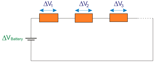
If we think about a circuit with multiple resistors attached in series and energized using a 2V cell, the overall depreciation of electric potential is 2V. Meaning , you will see some voltage drop around each individual linked resistor. However you will observe that the total voltage drop of all the parts is going to be 2V that is equal to the voltage rating of the power supply.
Mathematically, we are able to exhibit this: ΔVBATTERY = ΔV1 + ΔV2 + ΔV3 ........
By employing Ohm’s law the specific potential drops could be determined as
ΔV1 = I X R1
ΔV2 = I X R2
ΔV3 = I X R3
Now, let's imagine a series circuit consisting of three resistors and driven by a 9V battery source. In this article, we will determine the potential difference at various spots throughout the movement of current across the whole of the series circuit. The spots are designated in red coloration in the circuit beneath.
We realize that current moves in the path from positive port to the negative port of the supply. The negative indication of the voltage or potential difference symbolizes the drop in potential because of the resistor.
The electric potential difference of various spots in the circuit may be depicted by using a diagram known as electric potential diagram which is demonstrated underneath.
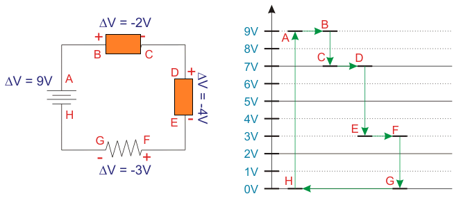
In this illustration, the electric potential at A is = 9V because it's the bigger potential point. The electrical potential at H is = 0V because it is at negative point. When the current moves via the 9V power supply, the charge acquires the 9V electrical potential from H to A. As the current travels across the outer circuit, the charge loses this 9V entirely.
This takes place in 3 ways. It will have decline in voltage as soon as the current moves over the resistors but there's no voltage drop while the charge moves through wire. Therefore, you observe that over the points AB, CD, EF and GH; we don't find any voltage drop. However at the points B and C, the voltage drop happens to be 2V.
Meaning the original source voltage 9V here turns into 7V. Now , if we consider points D and E, we find the voltage drop is 4V. Here, , the voltage 7V can be seen dropped to 3V. Ultimately, across the points F and G, the voltage drop appears to be 3V.
At this stage, the voltage 3V turns into 0V. The part of the circuit between the points G and H, you cannot find any strength for the charge. Therefore, it tries to find an energy supplement to travel across the external circuit yet again. It gets it from the power supply as the charge moves across H to A.
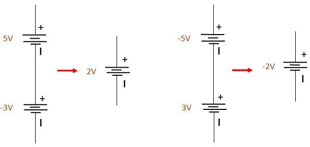
The number of voltage sources in series could be substituted with a solitary voltage source by using the aggregate of all of the voltage sources. However we need to be careful about the polarity as demonstrated below.
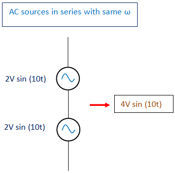
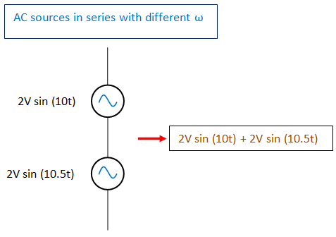
AC Voltage Sources in Series
When it comes to series AC voltage sources, the voltage sources could be summed up or combined with each other to create just one source on condition that the angular frequency (ω) of the linked sources are exactly the same. When the AC voltage sources hooked up in series have varying angular frequencies, it may be added in collectively only if the current from the linked sources is identical.

Voltage in Parallel
Parallel circuit or parallel network usually means when a couple of or more electrical equipment are connected together with their end terminals tied in a common network. In such a interconnection, each equipment is positioned in its individual unique department. Voltage, as we know accounts for the current to move within a closed circuit. In this post, we'll talk about comprehensively regarding voltage working in parallel circuit.
At this point, the various branches within a circuit indicates there may be a number of routes for the charge to travel to the outer circuit. When a charge extends to a nodal position, it quickly selects which branch it needs to divert through on its course in order to get back to the opposite potential port.
Let's contemplate a closed circuit having a voltage supply source and a resistor. Within this circuit, the current will probably move via the solitary route accessible. Then , within the very same circuit let's consider bringing a couple of additional resistors in parallel with the first resistor. This leads to several routes for the current to flow across, instead of a solitary route to arrive at the lower potential end.
Therefore, as we add more range of branches, net resistance reduces and it is apparent that the current inside the circuit tends to get proportionately higher. Meaning , the total current would be the final amount of the various currents across the three resistors.
Within the parallel circuit, we are able to observe that there exists a maximum of two units of electrically common points. That is; A and H, B and G, C and F, D and E in the circuit proven under. Voltage, that is calculated over the common points consistently always, must be identical.
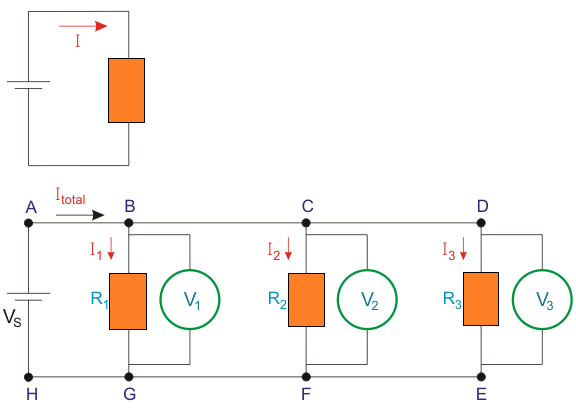
Within the above a couple of diagrams, first displays the close circuit having a voltage source along with a solitary resistor. Second diagram consists of parallel circuit involving 3 resistors and a voltage supply.
The voltage in this circuit is actually identical for all 3 branches and it is likewise identical to the voltage of the supply, which can be expressed as:Vs = V1 = V2 = V3
The sum of the currents in the mentioned parallel circuit is manifested by Itotal and it is presented as:
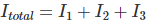
The total or productive resistance for this parallel circuit is:

Therefore, we are able to deduce that by adding more branches within a specified parallel circuit, the total current increases and the circuit may get beyond capacity.
Advantages of Parallel Circuits
When we would like to hook up a pair of bulbs with a solitary battery, you will find a couple of choices for us. Sometimes it could be joined like an array (in a series string) or may be in parallel. When we attach this like a string, the two bulbs are going to be within the same single conducting line between the two terminals of the battery. The difficulties using this network can be understood as given below:
- We are unable to switch on or use one bulb separately.
- Both the bulbs will probably be dimly lit because they are sharing a single supply source.
- When there is a issue in one of the bulbs, then the entire circuit will probably be impacted.
Conversely, if we are hooking up the 2 bulbs alongside or in parallel, both bulbs are certain to get the entire voltage from the battery. Consequently the advantages would be the as given below:.
- Each bulbs acquire 100 % level of voltage from the battery.
- We are able to work two bulbs independently.
- The two bulbs are going to be bright when switched on.
- When there is a problem in a single bulb, it may be taken out or fixed. Therefore, the whole circuit will never be impacted.
Parallel Circuits in Home
Just about all our home appliances are linked in parallel with one another. For this reason we are able to run each appliance independently without conflicting with each other. As an example, we are able to switch on washing machine without having involving the microwave or television.
We realize that within our house, the electrical wires includes three wires- Phase or LIVE, neutral and earth. For the present discussion we could disregard the earth and just focus on the phase and neutral wire. Voltage exists over the live and neutral wire that are hooked up eventually to some power plant source.
Every single outlet within our house is connected to these phase and neutral lines. Whenever we connect an equipment into this socket, it results in an electrical association on this socket. Each and every appliance includes a unique association across these electrical wires.
Therefore, whenever we turn on the device, the entire voltage is going to be available around it this means you will be able to operate each of them separately.