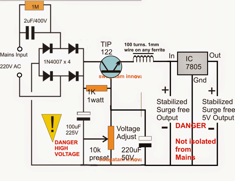
This article transforms a basic capacitive power supply into a safer and more versatile design. The resulting transformerless circuit will offer:
- Surge protection for handling unexpected voltage spikes.
- Constant Stabilized voltage output for consistent power delivery.
- Optional variable voltage for adjusting power to different devices (if needed).
This improved design will be suitable for powering a wider variety of electronic loads and circuits.
The idea was requested by Mr. David.
Technical Specifications
I remember mentioning the transformerless circuits on your blog a while back. I'm glad they worked out for me. I'm currently running a couple powering 20W and 30W LEDs!
Now, I'm working on a project with a controller, fan, and LEDs, and I need a dual power supply for it. Here's what I'm looking for:
- Dual Outputs:
- Output 1 (P1): 3.3-5V at 300mA (for controller)
- Output 2 (P2): 12-40V (or higher) at 300mA (for LEDs)
The challenge is getting the 3.3V output from your Circuit without adding another capacitor. I was thinking about a couple of options:
- Adding a separate circuit to the first circuit's output to generate the 3.3V supply.
- Placing a second triac and bridge rectifier in parallel with the first one, after the capacitor, to get the lower 3.3-5V output.
Any help you can offer on the best approach for this project would be greatly appreciated!
Thanks,
The Circuit
The various components work together in stages to achieve a controlled output voltage. Here's how they work:
The four 1N4007 diodes convert AC mains voltage to pulsating DC. A 10uF/400V capacitor smooths this pulsating DC.
A voltage divider circuit with a TIP122 transistor (MJE13005 for better safety) reduces the high voltage (around 310V) to the desired output level. You can adjust the output voltage (e.g., 12V) with a 10K potentiometer.
To prevent the transistor from turning on during initial switch-on and avoid surge damage, a 220uF/50V capacitor is used. The inductor also helps limit the inrush current during startup.
For a precise 5V output or other desired voltage levels, a 7805 voltage regulator can be added.
Circuit Diagram
Upgrade with MOSFET Control:
This emitter follower circuit can be improved by using a MOSFET source follower power supply. This new design also includes an additional current control stage using a BC547 transistor.
The complete circuit diagram for this upgraded version is shown below:
