


In the field of instrumentation we find DC supply being utilized for implementing analog representation of specific physical quantities such as weight, pressure, motion etc.
The reason being DC signals are constant all through the circuit which works in series across source to the load. The current sensing devices likewise feature less noise hence, frequently it becomes necessary to set-up current corresponding to a constant type of voltage.
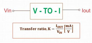
For this reason Voltage to Current Converters are employed. It can easily transform the carrier of electrical data from voltage to current.
Simple Voltage to Current Converter
When we discuss concerning the relationship between voltage and current, it becomes evident to refer to the Ohm’s law.
V = I x R
It is a known fact that as soon as we apply a voltage to a circuit containing a resistor, will result in the generation of a proportionate amount of current which will begin flowing through it.
Therefore, it is apparent that the resistor determines the amount of current flow for a voltage source circuit or in other words the resistor works like a basic voltage to current converter for any linear circuit.

The circuit diagram of a resistor that works like a basic voltage to current converter can be witnessed below. Here, the electrical proportions for example voltage and current are symbolized by means of bars and loop correspondingly.
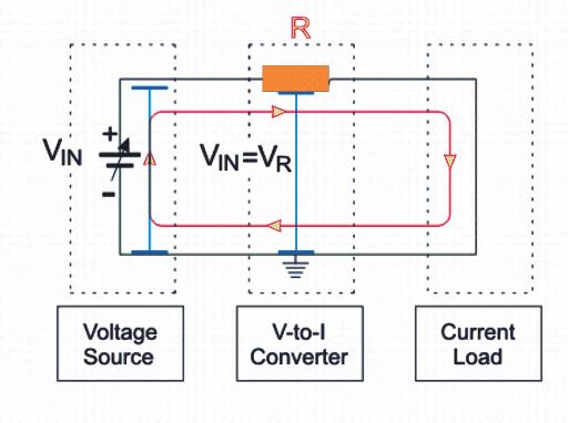
However essentially, the output current of this converter is based entirely on the voltage drop over the attached load besides the input voltage. Because of this, the circuit can be considered as a crude design or poor or a inaccurate passive version.
Voltage to Current Converter Using Op-Amp
Op-amp can be applied to easily transform a voltage signal to a respective current signal. The Op-amp intended for this objective is IC LM741.
This Op-amp is developed to carry the accurate level of current through the use of the voltage that is necessary to support that current via the circuit. They may be of a couple of forms which are discussed in greater detail below.
Floating Load Voltage to Current Converter
As the title signifies, the load resistor will be hanging in this converter circuit. Meaning , the resistor RL is unconnected with the ground line.
The voltage, VIN that is the input voltage is applied to the non-inverting input port. The inverting input pin is switched through a feedback voltage developed across the RL resistor.
This feedback voltage is established by the load current which can be seen in series with the VD, and this is developed by the input difference voltage. Which means this circuit can also be referred to as current series negative feedback amplifier.
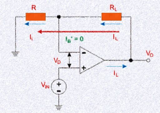
The equation for the input loop can b presented as:

The above equation proves that the load current varies according to the input voltage and also the input resistance. Meaning , the load current increases or decreases depending on the the input voltage.
The load current magnitude relies on the value of the resistor, R. Here, the constant of proportionality is indicated as 1/R. Therefore, this type of converter circuit is also called Trans-Conductance Amplifier. An alternate title of this circuit can be Voltage Controlled Current Source.
The specification of this load could be resistive, capacitive or nonlinear load. The quality or the property of the load becomes immaterial in the above equation if the load is hooked up in the form of a capacitor.
In that case it is going to get charge or discharge with a stable rate. Because of this reason, the converter circuit is implemented for the generation of saw tooth and triangular waveforms.
Ground Load Voltage to Current Converter
This type of converter is also referred to as Howland Current Converter. In this concept , one terminal of the load is permanently attached with the ground line.
For the circuit evaluation, we need to primarily identify the voltage, VIN after which we can establish or calculate the relationship between the input voltage and load current.

Therefore by applying Kirchhoff’s current law at the node V1, we get:

From the above calculations, we can finally assume that current IL has a relationship with the voltage VIN and the resistor R.