So the water level circuit idea we are proposing is really perfect for those of us who just want clear indications of the water levels and prefer to manually turn off the motor based on what the indicator shows and the desired levels we want in the tank.
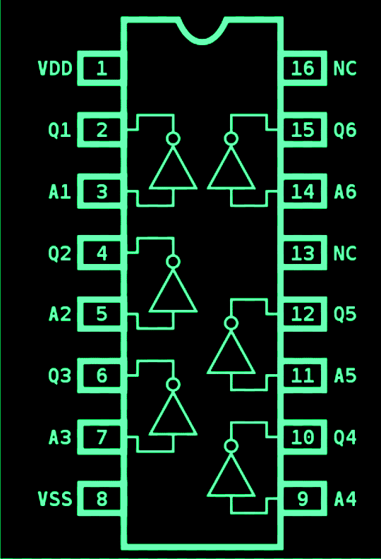
Now let me tell you that this circuit is super easy to put together. It only requires a single IC 4049 for everything we need to accomplish.
As we know the IC has six NOT gates inside it. These gates work as simple inverters which means they take any voltage level that we apply at their input pins and flip it to the opposite level at their output pin.
For example if we put a positive voltage into the input pin the output will immediately give us a negative voltage and if we apply a negative voltage then the output will give us a positive one.
One of the great things about CMOS gates is their high input impedance. This feature allows them to sense even very low currents effectively so that they can interpret what is happening accurately.
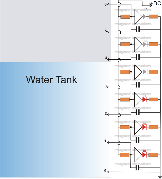
Now here is where it gets interesting, we keep the ground or negative voltage at the very bottom of the tank. This means that when we start filling up the tank with water it will reach this point first.
How it Works
As the water level rises it will come into contact with the inputs of our NOT gates that are arranged in a series going upwards. The negative voltage that is sitting at the bottom of the tank will leak through the water and connect with the relevant inputs of these gates.
When this negative potential touches the subsequent inputs of the gates it results in an opposite voltage being produced at their outputs which means we get a positive potential there. That’s exactly how it works.
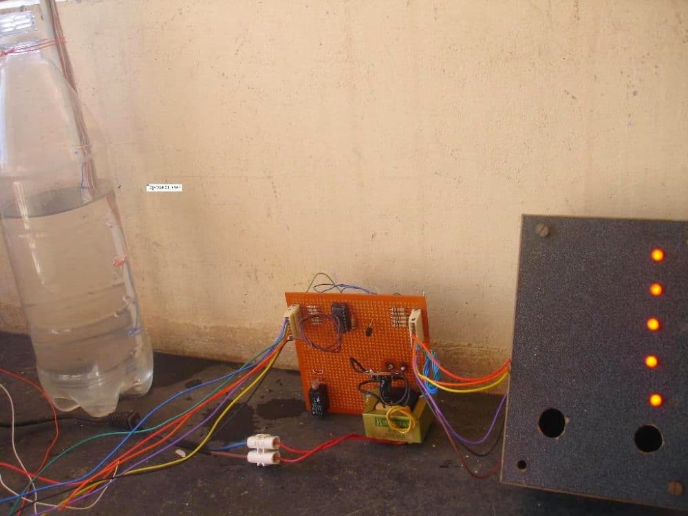
This positive voltage that gets generated lights up the LEDs we have set up, showing us which input of the gate has come into contact with the rising water level at what specific height.
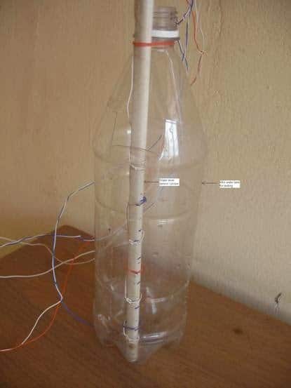
For our sensor wire terminals from this circuit which are labeled as points 0 to 6, we can arrange them on a non-conducting stick made out of plastic with brass screw heads attached as terminations for our sensors.
So when we see those LEDs lighting up it gives us a direct indication of where the water levels are since they are positioned at calibrated spots in the tank. You can check out the circuit diagram for more clarity!

The pin out diagram of the IC

Simulation
Now let’s talk about the simulation part. Below we have a rough simulation of the water level indicator circuit that we discussed earlier.
In this simulation we can actually see how the LEDs light up one after another as the water level rises and comes into contact with the different sensor points inside the water tank. Its pretty cool to watch how everything works together in response to the changing water levels!

Part List.
- All LED resistors are 470 Ohms,
- All gate input resistors are 2M2
- All capacitors are 0.1 disc ceramic.
- All the gates are CMOS NOT Gates
- All LEDs are red 5mm, or as preferred by the maker.
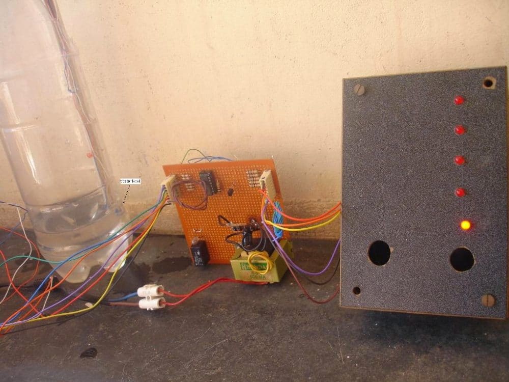
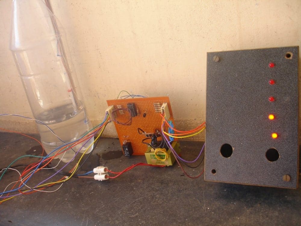
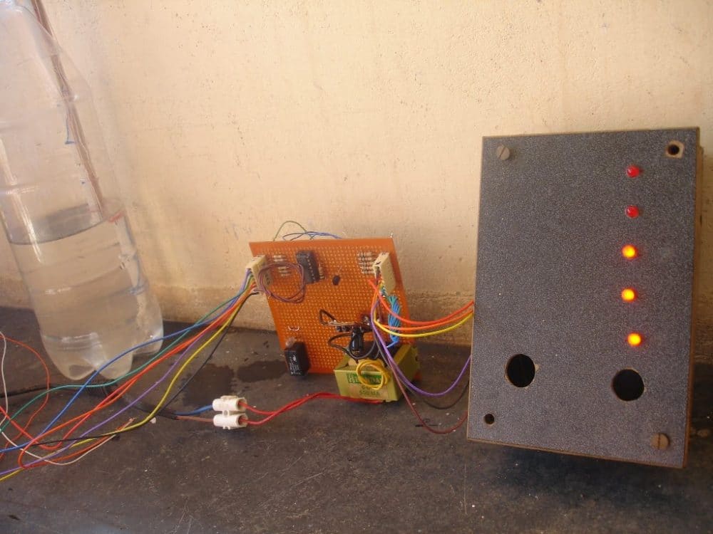
Practical Tested Prototype
So here is the exciting part: the circuit we talked about was successfully built and tested by Mr. Alex who happens to be one of our regular and dedicated readers of this blog.
He was kind enough to send us some pictures of the prototype he built, and we should definitely take a closer look at the results together.
Lets investigate into what he has accomplished with this prototype!