Many complex circuits and integrated circuits contain zero crossing detectors, but we will deal only with the detector here. The detector produces a pulse each time the mains voltage goes through zero potential.

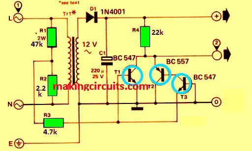
The circuit created is quite easy. It takes the mains voltage, rectifies it via D1, smooths it through C1 and produces a direct voltage of 17 V.
A portion of the mains voltage taken from across R2 operates the transistors T1-T3.
T1 continues to work while T2 and T3 switch off when the voltage is positive, while the reverse happens when the voltage is positive, ie, T1 turns off and T2 and T3 conduct.
None of the transistors work when the voltage lies between +0.6 V and -0.6 V.
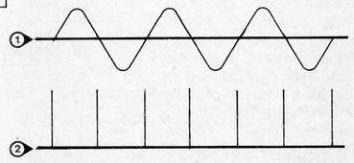
A short positive pulse is obtained as a result of the high output voltage produced due to this. There is no phase shift due to the isolating transformer since the circuit is driven directly by the mains.
If you are going to supply the direct voltage output to any external circuit, make sure the current is within the permissible limit of the circuit and also the TR1 transformer rating.
You may also have to increase the value of C1. Similarly, always keep in mind that this and any connected external circuits are supplied directly from the mains.
Waveform of zero crossing output pulse