


Through this publish we discover ways to make a clear-cut controller driver circuit for functioning 3 phase brushless DC motors.
The circuit implements the widely used IRS2330 3-phase driver IC
The offered concept appears very simple considering that almost all of the technicalities is looked after effectively by the IC itself, it's exactly about hooking up the appropriate pinouts with the few external additional parts for the preferred implementations.
We know that all BLDC motors simply incorporate Hall sensors linked to their stator assembly where these devices play an important rule in detecting and providing the control circuit with the needed data concerning the rotor magnet immediate positions pertaining to the stator coil activation.
The information can help the control circuit to eventually changeover the stator electromagnet activations in sequence such that the rotor consistently experiences a rotational torque and generates the meant rotational motion.
Consequently it appears that the hall consequence sensors are the ones that turn out to be exclusively accountable for detecting and activating the designed rotational motion in BLDC motors.
The control circuit associated with the hall sensors are in fact "blind" and react completely to the hall sensor signals to be able to create the needed feed backs to the electromagnet coils.
The above essential fact actually tends to make the creating of a 3 phase BLDC motor controller rather very simple, the simpleness also turns into additionally helped with the simple accessibility to the universal 3 phase H bridge driver IC for example the IRS2330.
The following information provides an extensive view on the developing of a 3 phase BLDC motor controller circuit:
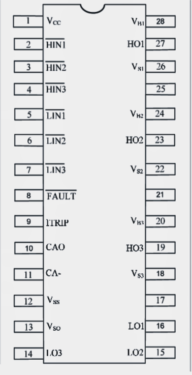
IRS 2330 IC pinout diagram


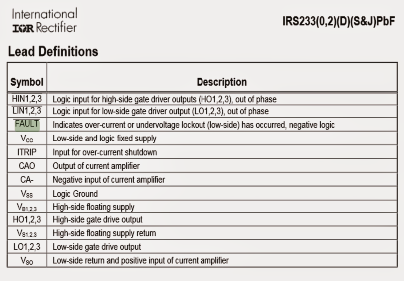
The above demonstrates the pinout diagram of the IC IRS2330 which basically ought to be linked to a couple of a couple of external elements for applying the offered BLDC controller circuit.

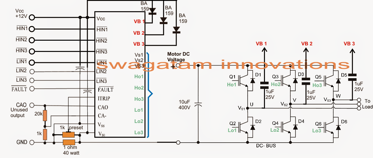
In the above diagram we experience the procedure for attaching the IC pinouts with some external features wherein the appropriate hand side IGBT stage displays a standard H bridge configuration utilizing 6 IGBTs built-in with the suitable pinouts of the IC.
The above integration concludes the output power stage for the BLDC controller circuit, the "load" implies the BLDC 3 phase electromagnet coils, now its pertaining to configuring the inputs HIN1/2/3 and LIN1/2/3 of the IC with the pertinent hall sensor outputs.
BLDC Hall effect buffer stage
Before applying the hall sensor causes to the driver IC inputs, it's needed to be buffered by means of several NOT gates as presented in the diagram above.
Finally, the outputs of the NOT gates is incorporated properly with the inputs of the IC IRS2330.
The negatives of all the hall sensors might be thought to be grounded.
The second circuit which forms the main driver configuration is likely to be also observed owning a current sensing stage across its lower left section.
The resistive divider could be correctly dimensioned for allowing an over current protection and control over the linked BLDC motor.
For obtaining complete information relating to the current sensing configuration and other complexities of the entire design, it is easy to seek advice from the following datasheet of the IC:
http://www.irf.com/product-info/datasheets/data/irs2330pbf.pd