


The submit provides a re-designed battery charger circuit concept which might be useful for improving 6V positive earth cars, aiding an external 12V battery to serve in them together with the current 6V battery with a standard positive earth body.

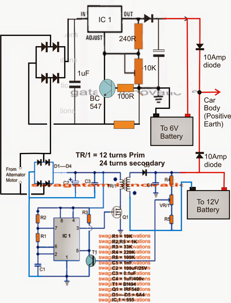
The diagram of the offered 6V and 12V positive earth car battery charger circuit demonstrates two separate stages comprise of one LM396 adjustable voltage regulator stage and another 555 IC dependent 6V to 12V increase converter stage.
The upper LN396 phase is set up to generate a changeable output selection of 1.25V to max based on the alternator voltage supply capacity, although the lower enhance converter is located to replace the 7V AC from the alternator to the needed 14V for charging an optional12V battery.
The 10K preset in the LM396 circuit might be modified for attaining a continuing 7V for the linked 6V battery. The resistor displayed relating to the base and emitter of the connected BC547 transistor functions as the current limiter. The value might be chosen according to the formula: R = 0.6 x 10/Battery AH.
The 555 IC boost circuit is liable for improving the 7V from the alternator to the essential levels for charging the associated 12V battery.
The preset VR1 could be fine refined to get the exact 14V across the battery.
The coil TR1 might be wound given below:
Core: 1 inch OD
Primary: 12 turns using 1mm magnet wire
Secondary: 24 turns using 1mm magnet wire