

Any time we think about regarding a set-up of electronic assemblies or repairs, it is typical to possess to have some test equipmentwhich is able to produce a specified amount of adjustable current. We could, no doubt, use power resistors that we can configure as per various series or parallel combinations, however this quickly turns into annoying due to its limitations. Additionally, no continuous adjustment is achievable, being forced to have a significant range of power resistances, making things rather troublesome. The circuit idea proposed here can be effectively used as an adjustable curent stage in any amateur laboratory, mainly because it enables to fix this matter in a really amazing way while keeping a low cost price.
It acts, essentially, as an electronic adjustable current from 0 to 10 A in a couple of ranges.
Therefore it can absorb any current between these two confines and with any voltage placed on it that is between 3 and 80V. To sum it up, this construction addresses the majority of the regular requirements in this field.
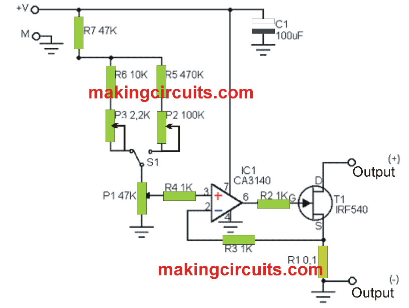
The theory of the design is pretty easy to comprehend once you analyze your circuit diagram. The actual load is constituted by the MOS transistor, or T1, which will be pretty much conductive working on its gate voltage. To determine the current that travels through it and, consequently, the current that is consumed by the load, the voltage drop which it produces across the low value resistance R1 is referred upon by the opamp.
The IC2 integrated circuit, is rigged as an enhanced zener by incorporating some electronics, which lets an incredibly stable voltage of 1.2V to be developed at its terminals. This voltage is generated the non-inverting input of IC1 following attenuation by different voltage divider stages to resistors and potentiometers.
The inverting input of IC1 obtains the voltage deduced on the terminals of R1; voltage that is, as a result, proportional to the current consumed by the connected load. According to the standard rule of the operational amplifier, the latter then generates an output voltage that, takes care to ensure almost that all of its input voltages, causes T1 roughly conductive with respect to the demands. The switch S1 enables to have 2 working ranges employing a voltage division rate governed by IC2 pretty much significant. The potentiometer P1 deduces an adjustable fraction of this voltage, thereby permitting a continuous adjustment of current to the sine of the selected range.

Parts List
IC1: CA3140
IC2: ICL8069
T1: IRF540
R1: 0.1 20 W
R2 to R4: 1K 1 / 4W 5%
R5: 470K 1 / 4W 5%
R6: 10K 1 / 4W 5%
R7: 47K 1 / 4W 5%
C1: 100uF / 25V
P1: rotary linear potentiometer to be implanted over IC of 47 K
P2: vertical adjustable potentiometer for CI of 100K
P3: vertical adjustable potentiometer for IC of 2.2K
S1: switch 1 circuit, 2 positions.