

In telecommunication devices, the squelch circuit is introduced in order to enable the suppression of the audio (or video) output of a receiver whenever a low or weak signal input is detected.
This circuit attenuates the background noise that is present between the transmissions and when tuning an audio amplifier system. Moreover, another function of the squelch circuit is as a power amplifier (with built-in squelch) for a homemade receiver, constructed for headphone use only.
This circuit is also for enthusiasts who’d love a squelch on their radios.
The following figure depicts a circuit that produces a squelch and can be linked between a receiver’s audio output and a speaker.

How the Circuit Works
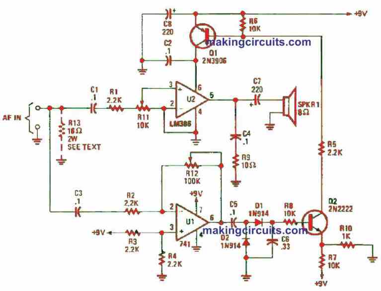
The core of the circuit are two ICs, namely the LM386 low-voltage audio amplifier and a 741 general-purpose op-amp. The former delivers drive for the external speaker and the 741 op-amp regulates the squelch’s edge level.
The receiver’s audio signal is supplied to the input side of both IC amplifiers. Op-amp (U1) is capable of amplifying the audio at its input by up to 45 times, as configured by the value of the threshold/gain control, R12.
The output of the op-amp at pin 6 is changed to DC by diode D1 and D2. This produces a positive DC signal which is applied to the base of Q2, forward biasing it.
At the junction of R7 and R10, the voltage triggers the emitter of Q2 to around 1 V at bias level. Once the DC voltage at the base of Q2 elevates to more than 1.6 V, Q2 will be activated. Then, Q2’s collector pulls R5 close to ground potential which in turn triggers Q1.
This action start powering up the LM386 audio amplifier. As a result, the audio signal is enhanced and channeled to the speaker.
A constant average input signal will permit U2 to remain on. However, once the audio falls just enough to abruptly stops, the process will reverse and U2 switches off. At this moment, the values of C6 and R8 will determine the time constant for the turn-off delay period.
How to Build
Construction of the squelch circuit is fairly easy and can be done on a perfboard.
Once done, you can easily house it in a small metal or plastic case.
For the supply voltage, you can use any 9 to 12 V DC source that can deliver up to 100 mA. This is enough to power the circuit.
How to Test
Application of the squelch circuit is also simple. All you need to do is attach the squelch’s audio input to the receiver’s external speaker output. After that, you must combine the R13 (16 ohm, 2 watts) resistor between the positive signal input and ground, as depicted in Figure 2.
The dashed line which indicate the resistor is only required when the squelch circuit is attached to an output functioned to drive a speaker.
Configure R12 for its peak resistance and R11 to around mid-range. As the squelch circuit disconnected, navigate to a strong station and tune the receiver’s volume for an optimum listening level.
Reconnect the squelch circuit and modify the R11 again for the expected volume.
After that, turn R12 to its minimum resistance level and the audio should switch off. Now, you have to gradually tune the receiver to another station and the audio should turn off between stations.
Once the signal is strong and constant, the audio should return. Playing around with the value of R12 will assist in getting the desired squelch action.
If you need to prolong the time that the audio stays between signals, you just need to increase the value of C6. Reverse the action if you need to lessen the time.