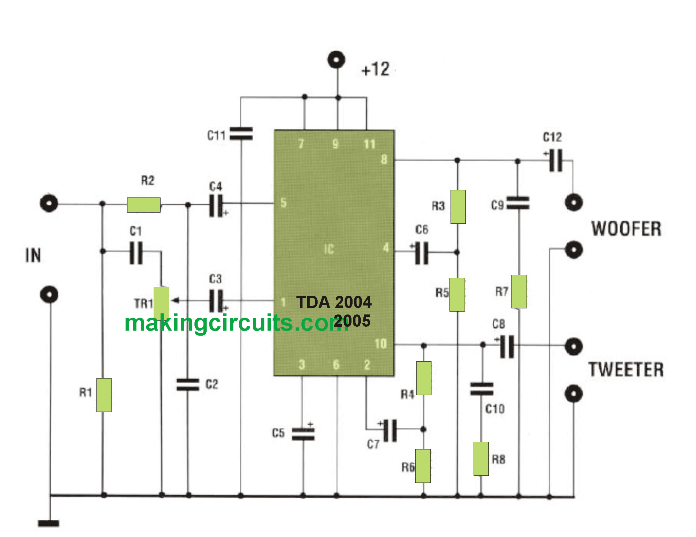
If you are planning to make an speaker amplifier box circuit or ampli-speaker unit with integrated woofer and tweeter, this circuit will help you to reach your goal with great success and also very cheaply.

It is an amplifier which, with a voltage of 14.4 Volts, distributes a total power of 20 Watts in two different channels to which are connected as TWEETER and as WOOFER respectively.
This proposed 20 watt speaker box amplifier circuit is therefore equipped with an active CROSS-OVER filter with a crossover frequency of 2 KHz.
Each loudspeaker must support a power of 10 Watts and have an impedance of 4 Ohms.
The trimmer TR1 allows the best acoustic rendering of the power of that. Output of the treble channel. The supply voltage is adjusted to be between 12 and ges-tive up to 15 volts.
This buyit-in woofer/tweeter speaker amplifier circuit can be also advantageously used as a BOOSTER for 2-way radio. In this case, a resistance of 3.3 kOhms must be interposed between the output of the car radio and the input of the amplifier. In order to avoid unpleasant distortions, signals above 50 mV must be avoided. In order to assemble the components, the implantation diagram must be followed.
Parts list for the speaker box amplifier circuit:
All resistors are 1/4 watt unless otherwise stated.
R1 = 680 Ohms
R2 = 10Kohms
R3 = 1 Kohm
R4 = 1 Kohm
R5 = 10 ohms
R6 = 10 Ohms
R7 = 10hm
R8 = 1 Ohm
TR1 = 10 Kohms trimmer
CI = 5.6 nF ceramic.
C2 = 5.6 nF ceramic.
C3 = 2.2uF16Velec.
C4 = 2.2uF16Velec.
C5 = 2,2uF16Velec.
C6 = 100uF16Velec.
C7 = 100uF16Velec.
C8 = 100uF16Velec.
C9 = 100nFpol.
C10 = 100nFpol.
CII-lOOnFpol.
Cl2 = 2200uF16Velec.
IC1 = TDA2004-2005
1 Heat sink.
Leave a Reply