


LEDs are a lot economical in comparison with ordinary incandescent lamps or maybe the latest halogen lamps in relation to their performance, luminance and life.
For that reason even in automotive field we could now observe a speedy transition from the old filament sort of bulbs to the advanced high bright LED lamps.
These have been generally being applied as brake lights and head lights in most modern and the new generation vehicles.
In the recommended automotive brake light circuit 1 watt high efficiency LEDs are widely used to for carrying out the really high level of illumination.
It is well known that generally today's all of the advanced high watt LEDs prefer two significant limitations so as to feature appropriately and safely, particularly a current controlled supply and thermal or heat regulated assembly.
The first criterion could be applied by means of any kind of modern superior linear IC for instance a LM338, I have talked about it elaborately in one of my prior posts high watt LED current limiter circuit.
For the second condition one can easily use a special aluminum base PCB fitted on a heatsink for assembling the 1 watt LEDs.
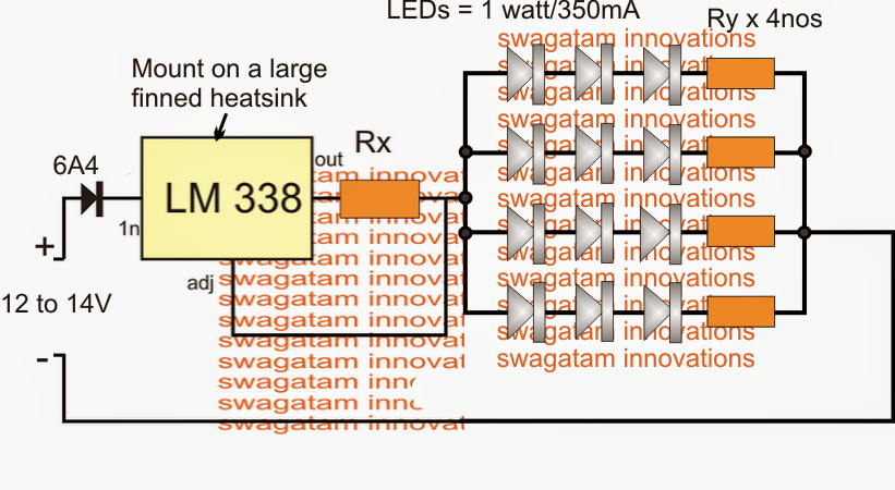
automotive LED brake light circuit making use of 1 watt high efficiency LEDs
The circuit for the LED brake light could be noticed above, and it seems to be pretty straightforward.
The LM338 is designed as a current limiter, where Rx establishes the optimum allowed amps to the attached LEDs. It could be measured by making use of the following formula:
Rx = 1.25/LED current
When LeDs are attached in series there effective current usage is usually similar to the rating of the one individual LED. For that reason in the diagram each string could require 350mA since this is certainly the rating of each 1 watt LED.
Paired current for all the three strings could well be 3 x 350mA = 1050mA or somewhere around 1 amp
Substituting the above parameter in the formula we have:
Rx = 1.25/1 = 1.25 Ohms
Wattage = 1.25 x 1 = 1.25 watts
The resistors Ry which may be viewed attached in series with the LEDs are generally optional, these could be involved only for supporting the IC and supplying correct balance across the LED strings.
It could be measured making use of the following formula:
Ry = (Supply - LED total FWD voltage) / LED current
Since here the LEDs are specified with a forward voltage of 3.3V and 3 nos are set up in the range, the combined forward voltage evolves into 3 x 3.3 = 9.9V
For reducing full loading of the LEDs, we could require the current at 300mA in place of the particular 350mA
For that reason Ry = (13 - 9.9) / 0.3 = 10.33 ohms or simply 10 Ohms
wattage = (13 - 9.9) x 0.3 = 0.93 watts or 1 watt
Seems like we overlooked an essential inclusion in the above diagram, it's the dimmed LED feature in the course of the standard course of the vehicle and while the brakes are not employed.
The following diagram recommends how merely this can be applied making use of a equivalent attached resistor Rz, with Rx.

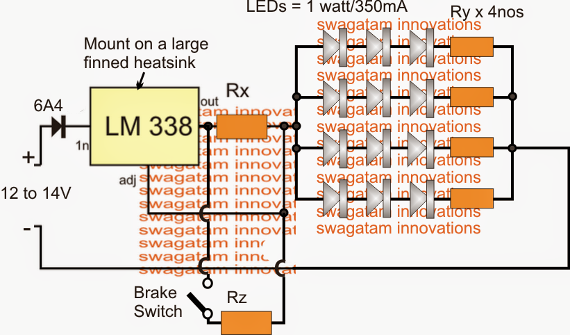
LED brake light circuit dimming when vehicle is operating without brakes
Here the values of the Rx and Rz could be similar still double that of the above measured value that is 1.25 x 2 = 2.5 Ohms. This may enable a 50% dimming of the tail lights while the brakes are in the released position.
If one would like to gain further dimming of the LEDs Rx could be increased to 3 ohms or 3.5 Ohms, this may also mean lowering the Rz value proportionately such that the parallel value of the two resistors constitutes 1.25 Ohms.