


In this particular post we be familiar with an easy battery current sensor with indicator circuit which identifies the amount of current utilized by the battery while charging or by any other load and displays it by way of discrete LEDs.
Universally most battery charging indicators make use of the voltage level of the battery to show its charging condition, here in place of voltage the current (amps) magnitude is employed for measuring the charging level.
Making use of current as the measuring parameter helps a more correct assessment of the battery charging level. The circuit is furthermore efficient at suggesting the instant health of a attached battery by translating its current utilizing capacity while its being charged.
Making reference to the presented circuit, you can observe four opamps configured as comparators exactly where each opamp carries it own presetable current sensing inputs.
A high watt resistor Rx forms the current to voltage converter component which experiences the utilized current by the battery or the load and converts it into a associated voltage level and draws it to the opamp inputs.
P1 upto P4 are adjusted such that the A1 to A4 opamp non-inverting inputs develop into greater than their particular inverting inputs in accordance with the lowering current consumption by the battery as it actually reaches it full charge status.
As an illustration P1 could be adjusted such that A1 pin3 evolves into moderately greater than its pin2 when the battery utilizes the highest amount of current (a known specified level), that could be when its fully discharged.
P2 could be adjusted equivalently when the battery gets charged to quite a few a rather higher voltage level and its current usage is lowered consequently.
In the same way P3 and P4 could be adjusted for the next lower voltage levels across Rx as a reaction to the battery's increased charge level until it's fully charged.
These kinds of different current consumption levels from maximum to minimum is suggested by the matching LEDs attached across the outputs of A1 to A4 in a sequential manner, through which only a single LED lights up at any kind of provided illustration for suggesting the applicable battery current levels.
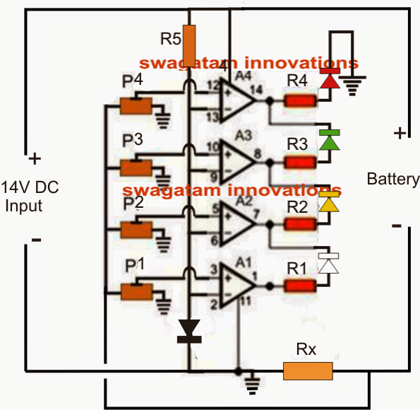

Parts List for the offered battery current indicator circuit
R1----R5 = 1k
P1-----P4 = 1k presets
A1-----A4 = LM324 IC
Diode = 1N4007 or 1N4148
Rx = 0.6/specified battery charging current
Easy methods to start up the circuit
In the beginning continue all the preset slider arms on the way to the ground end.
Disconnect the P1---P4 connection with Rx and connect it with an external variable voltage source which might be simply made with a 1K pot.
For creating the variable power supply, take a 1K or a 10K pot, connect its outer terminals with the supply rails and connect its center terminal with the free end of P1---P4 which was shut off from Rx.
Adjust the pot and create a 0.7V at the center lead of the pot.
Now adjust the P1 such that the white LEd just glows.
Increase the pot center lead voltage to 1V and set P2 such that the yellow LED just glows, shutting off the red LED.
Next, increase the pot center lead voltage to 1.3V and after some time to 1.5V and adjust P3 and P4 likewise as done for P1, P2.
The moment the setting is performed the pot can be eliminated and the P1----P4 end reconnected to the Rx point.
The above range of 0.6V to 1.5V will likely be subject to the picked Rx value as well as the needed current range, where 1.5V could be realized to the maximum voltage across Rx created for the same maximum required charging current for the battery or almost every other load.
As an illustration, a 1 ohm resistor elected for Rx will create 1.5 V across it when a current of 1.5 amp is passed by means of it, whereas the same voltage will likely be created for a 5 amp current if Rx is picked as 0.3 ohms etc.
The formula for locating Rx = 1.5/maximum charging current.