

Commonly found in simple devices like an IR remote control unit and calculators, the battery protection circuit serves to limit the over-exhaustion of battery power in the event you forgot to switch off the device. Still, the batteries will deplete no matter how low the standby current is in these devices.
This battery saver circuit in discussion automatically cuts off the supply current one minute after power-on, or once the battery voltage drops below the nominal level of operation.

How it Works
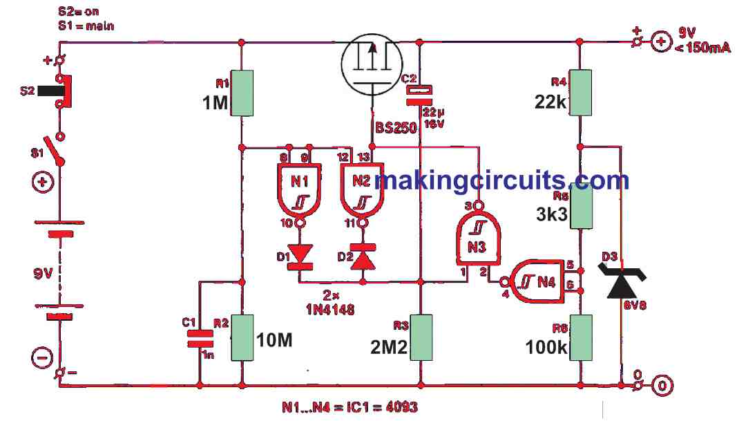
A series regulator FET T1 can permit a maximum current of 150 mA in the circuit. Moreover, we recommend using a more powerful kind of FET than the BS250 in the event more than 100 mA is expected to be utilized by the equipment attached to the output terminals.
This type of FET dips around 0.5 V at a drain current of 0.1 A, and 0.8 V at 0.15 A. Because the T1 is a p-channel FET, it conducts and supplies the equipment once the output of the Schmitt trigger NAND gate N3 is low.
In other words, when the gate inputs are high. This occurs at power-up because C2 is still discharged and the N4 inputs are kept at logic low level through R6.
As a result, T1 is activated and causes C2 to be charged through R3. After one minute has elapsed, the voltage across R3 will be fairly low for N3 to identify a logic low level at pin 1.
Consequently, it turns off T1. A locked function of this state is provided by N2 as otherwise, N3 could oscillate due to the steadily changing voltage across R3.
During power-on, N2’s output is pulsed high from the R-C network R1-R2-C1. Any residual charge in C2 is cleared and the circuit may be turned on with switches S2-S1 immediately after powering down and saving precious battery power automatically.
D3, R5, R6 and N4 successfully monitor the battery voltage. N4’s trigger threshold level is positively related to the supply voltage level of the IC.
Whenever there is the supply voltage (battery) and relatively high, N4 will identify a logic low level at junction R5-R6-N4. In the event, the battery voltage drops, the input voltage to N4 is maintained at a secure level by D3.