


The post describes a car power window controller circuit making use of a single push button or a few push buttons.
Window Glass Up/Down Controller implementing a Single switch
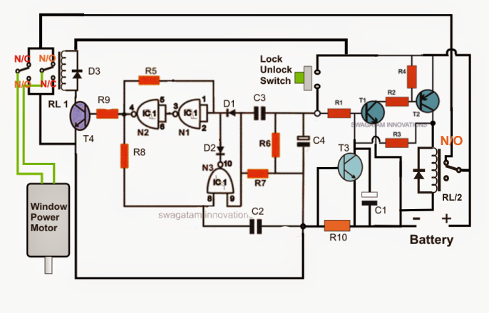
The demonstrated car power window controller circuit fundamentally involves three stages: a transistor latch including a current sensor, a NAND gate based flip flop stage and a relay driver stage for flipping the motor actions alternately.
The pointed out lock/unlock switch toggles the flip flop stage created by participating three NAND gates from the IC 4093, whose output replies with a long term high and low alternately with every push of the switch.


Parts list
R1, R3, R6, R7 = 100K
R5,R8 = 2M2
R9 = 4K7
C1,C4 = 22uF/25V
C2,C3 = 0.22uF
T1,T3 = BC547
T4= 8050
T2 =8550
RL1,RL2 = 12V/20AMP
ALL DIODES = 1N4007
R10 = TO BE CALCULATED
N1---N3 = IC 4093
This switch additionally ensures that the latch section consisting T1 and T2 gets triggered to be able to permit the supply voltage to achieve the remaining section of the circuit.
The output from the flip flop obtained at N2 pin4 is provided to a relay driver stage for signaling the power window motor with a forward or a reverse motion based upon the position of the window glass.
It has got to be guaranteed that while hooking up the motor the polarity of the wires are set such that a high at pin4 of N2 actuates the window in the closing mode, and vice versa.
The relay is a heavy duty DPDT relay whose N/C, N/O contact connections with the motor allow the motor to perform the needed to and fro motion.
Generally, reed switches are being used for detecting the the finish of the glass up and down actions in an effort to prevent the motor from obtaining loaded and damaged, in spite of this here we certainly have a captured another and a much sophisticated method.
In the recommended car power window controller circuit we now have used a current sensor stage by means of T3, which identifies a mounting current across R10 and switches ON itself when the level crosses a set threshold. When T3 switches ON it breaks the T1/T2 latch disconnecting the supply to the motor.
In spite of this if a reed switch is integrated for the above activities, the reed contacts located for detecting the up and the down thresholds of the glass might be wired across C1, and T3 stage could be taken away completely. R10 might be restored with a wire link (see figure below).

Making use of two switches
The above design could possibly be a lot less complicated if two separate push buttons are suggested for the up/down operations of the window glass. The less complicated power window circuit which includes just a few number of BJTs may be observed below.

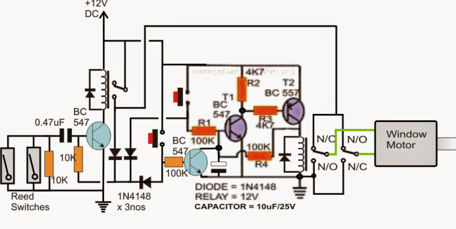
Four of the above circuits will have to be placed on each door of the vehicle for the preferred power window switching.
Within the next write-up we are going to talk about the brake switch controller stage for the above described design.
