


A car electrical is usually a lot more unstable than our house electrical, just because it is produced from a source called alternator whose output significantly differs with the speed of the vehicle. It implies if you happen to be driving your car with unexpected alterations in its speed or if you are often making use of brakes, would certainly accordingly produce various voltages from the alternator outputs.
Seeing that these days our car and other vehicle interiors greatly include advanced electronic gadgets, an unstable voltage circumstances may cause severe influence on their overall performance and life. A basic voltage stabilizer circuit for cars described here might basically reduce us from all the nervousness.
let's get more information regarding the producing of the offered circuit (created by me for the application).
At present we certainly have some fantastic ICs at our disposal which can be created specifically for voltage regulation applications.
The LM317 and the LM338 are a few them which are usually extremely versatile with their voltage regulation functions, I know mentioned them elaborately in a number of my previous articles.
The LM317 can manage up to 1.5 Amps while its big brother the LM338 are able to carry not a lot more than 5 Amps.
In spite of this these types of values are extremely meager in comparison with the large suggests in automobiles.
By surely adjusting the configurations, the IC can be created to control any preferred levels of currents although.
In the suggested car voltage stabilizer circuit we combine the IC LM317 and change its regular design such that it allows the car electrical with adequate power and yet limits it from all feasible threats like overloads, over current, fluctuating voltages and short circuits, offering the best voltage situations for the vehicle interiors.
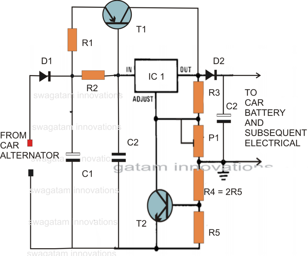
The circuit diagram exhibits somewhat effortless design where the IC 317 continues to be wired in its normal voltage regulator mode.
R1 limitations the surge current, while R2 chooses the initiating voltage to T1, if the current consumption exceeds the 1.5 amp mark, T1 performs and helps out the IC by discussing the excessive current by means of it.
P1 is set for attaining around 13 volts across C3.
R5 displays over load problems and short circuits, if the current exceeds beyond 12 amps, enough current grows across R5 to activate T2, which immediately switches OFF the IC in order that the output voltage falls and prevent the current below 12 amps.
Ideal Specs:
Constant voltage = 13 volts
Current Limit = 12 Amp
Overload protection = above 12 amp cut OFF
Thermal protection (if the transistor and IC are installed on the similar heatsink with mica isolation)
Short circuit protection (fire hazard protection)


Parts List
R1 = 0.1 Ohms, 100 watts, made from 1mm iron wire.
R2 = 2 Ohms, 1 watt,
R3 = 120 Ohms, 1/4watts,
R4 = 0.1 Ohms, 20 watts, as described for R1 (this resistor is really not needed, might be restored with a wire short.)
R5 = 0.05Ohms, 20 watts, make as R1
T1 = MJ2955 mounted on big finned type heatsink
T2 = BC547,
C1 = 10,000uF, 35V
C2 = 1uF/50V
C3 = 100uF/25V
P1 = 4k7 preset,
IC1 = LM317
D1, D2 = 20 amp diode (3nos. 6 amp diodes in parallel)
Simplified Version
Making use of the IC LM196, the above configuration turns into very simple, you might refer to the following diagram which demonstrates a less complicated version of the suggested car alternator voltage stabilizer circuit utilizing least amount parts.
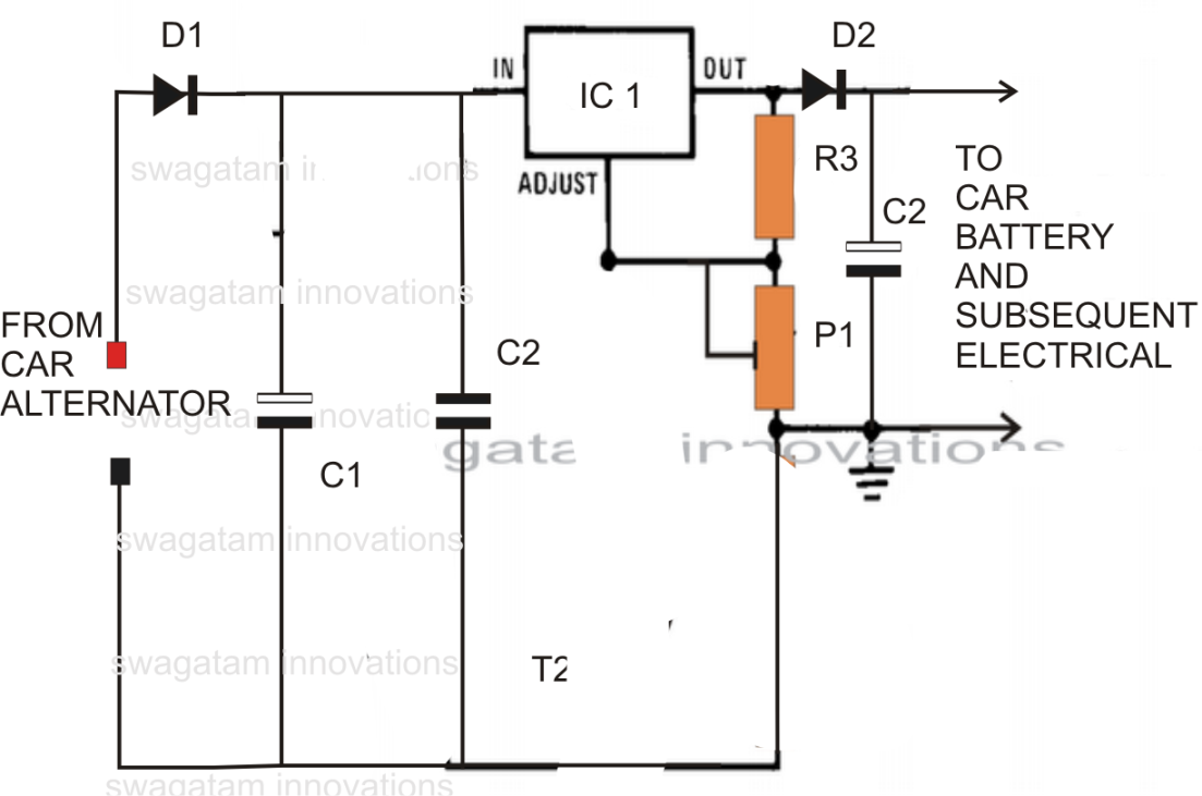
R3 = 240 ohms
D1, D2 = 15 amp diodes
P1 = 10k preset
C1,C2,C3 as specified above
IC1 = LM196
