Building an automatic light for washroom is not at all complex. All you need to do is to follow the steps as described in this report to get the derived result. Using an automatic switch would help to save electricity. Moreover, the system is designed in a way to run on lesser power, thereby saving your pocket!
Consider a situation – you enter into the washroom and the light turns on automatically; as you move out the light turns off! Yes, we are talking about an automatic switching solution for the washroom. With this solution you don’t have to worry to keep check on the washroom light, which we often forget to switch off at times.
How it works
The operational procedure of this effective device is simple. When one steps into the washroom, the system automatically detects the presence and turns the light on. As soon as the person leaves the washroom, the system again detects the absence and turns the light off.
How to build the proposed automatic light circuit for washroom?
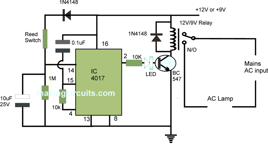
The following diagram in Figure details the way the circuit is built:

The primary component that you need to develop the system is the reed switch. This switch comes in two type, and we will use the one that shuts-off in normal state and turns on with the effect of magnetic field. 9V power supply is applied to the circuit – Pin-16 of 4017 IC has 9V and Pin-8 is left on ground state.
As a comparator, the circuit uses op-amp IC 741 and is defined in such a way to maintain high output state when the washroom door remains closed. The automatic washroom light circuit is further strategically placed onto the door so that it can come close to the reed switch when the door closes. Furthermore, the IC 4017 is deployed in a way to act on both instance – door open or close. So, the next time when the washroom door is opened and closed, the circuit cuts the relay making the light to extinguish. While IC 4017 is designed to handle nine counts, here we have applied only two counts and then reset. Because of the IC’s capacity to manage count value, here we have used it as one-bit counter.
As the washroom door opens, the reed switch initiates and the output of the IC 741’s sixth pin goes high, and as the door closes Pin-6 goes off. Again when the washroom door is closed, this enable triggering of the decade counter of IC 4017, and thus the relay helps toggling the system in ON and OFF state every time the door is opened or closed.
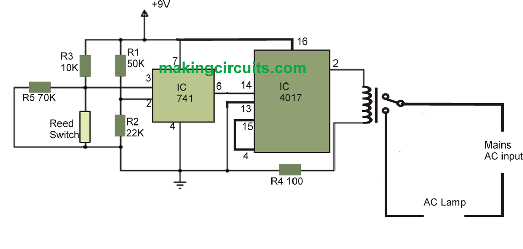
Improved Corrected Version of the above described automatic washroom light circuit
As you may note that the above explained design is full of flaws, it was taken from another site and it seems that the designer of the circuit has no knowledge of electronics.
First of all a IC 741 is not required for the reed switch operation in response to the door closing or opening.
Secondly, the relay should not be connected directly to 4017 output, must be done through a transistor driver.
Third, the output from IC 4017 must be taken from pin#2, and not from pin#3.
Fourth, pin#15 must be configured with a resistor/capacitor network as shown in the below corrected version: