

In this write-up we discuss a comprehensive circuit which allows the user to convert heart beat pulses into loud audible sound from a connected buzzer.
Thus , the design could be effectively utilized for listening to a patient's heart beats without depending on cumbersome stethoscopes or complex visual devices.
Introduction
Relying on the fact that blood supply pulsates at the frequency of the heartbeat, the circuit in the discussion is designed to determine the flow of blood through a finger.
Considering measuring errors like the position of the finger and inconsistent motion, the receiver diode is placed in a loop.
How the Circuit Works
Terminal 3 (positive input) of IC1 is maintained at around 2.5 V while the ratio R5: R4 decides the gain of the device. Furthermore, network R6 to D4 warrants the circuit is steadied quickly while IC2 rectifies the amplified signal.

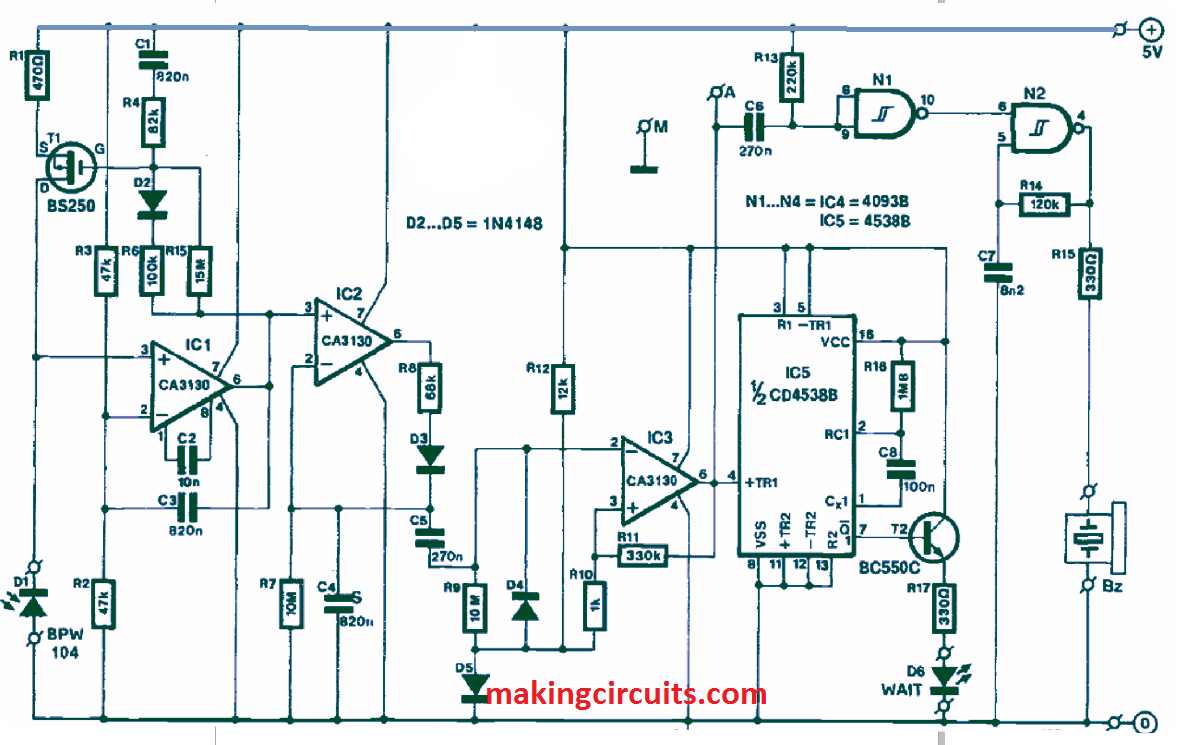
To enable a sawtooth shape of the voltage at pin 2 of IC2, time constants R8 to C4 and R7 to C4 are chosen.
The trigger is activated by CA3130 in the IC3 position. You can feed the output signal to the input socket of a computer. Alternatively, you can hear the beat using a piezoelectric buzzer functioned by gates N1 and N2.
To let know the circuit has steadied and suitable for use, a WAIT signal is given by IC5.
The first programming step is to wait for a trailing edge before counting for the next trailing edge.
Afterwards, the counts are transformed into a certain number per minute and presented on the screen.
But the heartbeat rate can be inconsistent, and that may be apparent from hearing the buzzer or looking at the monitor screen.
So, it is recommended to calculate an average of 60 seconds before recording the rate.
Then, it is possible to present the immediate value, its 60-second average and if there is a rising or falling trend.
When the program works correctly, the actual signal can be displayed clearly on the screen.
What is more, if an analogue-to-digital converter is used, the output signal of the IC1 may be directly utilized for the display.
Warning: The device should not be considered to be a medically approved heart beat monitor circuit. It may be used only for fun and casual experimentation