

This straightforward circuit is developed for controlling all forms of high current DC motors that is rated up to 40 A. Fundamentally, it’s just a standard oscillator triggering a handful of power MOSFETs.
The oscillator is a basic RC-type about a sole Schmitt trigger component (IC1a) from a 40106 hex inverter package. When the wiper is actuated in the direction of D2, potentiometer P1 provides peak voltage to the output. The two diodes safeguard the circuit from short-circuiting the output to the input. At the limits of P1, there are minimal discharge and charge times. We found the negative-sliding pulse is about 1 µs and 1.6 µs for the positive side when evaluating the prototype.

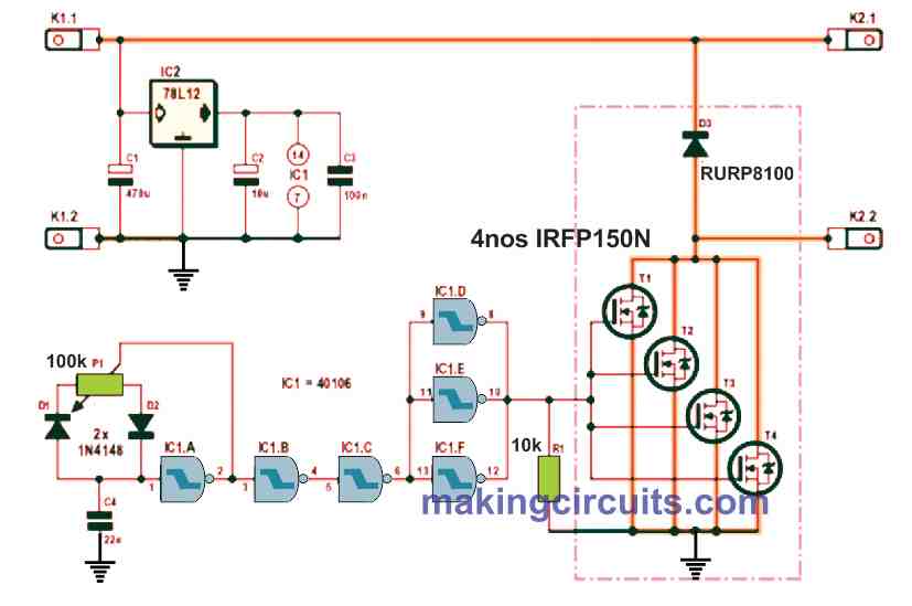
Inverters IC1b and IC1c filters the oscillator signal and ramps a buffer stage which contains three inverters connected in parallel, IC1d, IC1e and IC1f. To contain the MOSFETs in the absence of 40106, resistor R1 was included. The sum of the input drive capacitance of the four MOSFETs is close to 8 nF.
This value is excessive for the buffer to fully charge and discharge when P1 is switched to its extreme points. In a way, this is useful because practically it permits the high current motor driver to control the full output voltage span of from 0% to 100%.
The operating frequency set for this circuit is 1 kHz but, on the prototype, 1.07 kHz was recorded. Diode D3 at the output limits the reverse energy (back emf) produced by inductive loads which are all the DC motors. Substantial output currents and back emf are problems.
When testing with an earlier prototype, the rails to D3 were too slim. Furthermore, when experimenting the high current motor driver circuit with one of the motors, one of the rails suffered a burnout. Both motors used in the Wheelie when fully loaded consumes 20 A at 24 V. the circuit was examined at 40 A and 24 V with a resistive load.
Still, the constructed PCB was not able to manage such extreme currents. One of the solutions is to enhance the copper rails channelling high current flow with 13 or 14 AWG (2.5 mm2) copper cables.
Two paralleled parts of 16 AWG (around 1.5 mm2) may be more convenient to fit them into place. Because of that, the PCB is void of solder stop masks. The layered lines in the schematic present an easy identification of the expected travel locations of the high currents. A 78L12 voltage regulator delivers power for the 40106 using its standard decoupling capacitors.
You may attach the speed--regulating potentiometer off the board and linked with simple wires. It is also recommended to attach a heatsink to the PCB with 3-mm (6 IBA) screws.
You have to ensure the heatsink is insulated with the solder pads for the MOSFETs. After that, find the right positions for the transistor mounting screws, and D3. You can bend the transistors’ legs using a special tool to avoid mechanical stress. Only then, you should locate the placements of for the holes. The threading for this hole is 3-mm (around 1/8”, 6 BA) so you must tap it accordingly.
We highly recommend you double-check if all the semiconductors are isolated on the heatsink. There is a possibility that you will hear a faint whine from the DC motor because of the low switching frequency. This is normal and nothing to worry about.