

The post explains a schematic design of a versatile, Hi-End work bench power supply whose output voltage and output current can be independently adjusted very finely, with high accuracy and stability.
The circuit diagram of the single-channel power unit is presented in following figure. The output current is generated by Tr2, Br1 and C2. The output voltage is governed by a series regulator wherein T5, T4 and T7 are the active components.
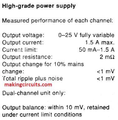
Main Feature
The main features and working specifications of this high end work bench power supply circuit can be learned from the following table image.

How the Circuit Works

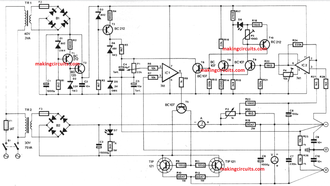
Essentially, all these transistors work like a multi-stage emitter-follower which is operated by opamp IC1. The current gain and the inclusion of Darlington power transistors for T4 and T7 guarantee a lower current requirement on IC1.
Transistors T4 and T7 are hooked up in parallel using a small emitter resistors to disperse heat dissipation. The output voltage of IC1 is decided in the beginning with a reference voltage used to its non-inverting input.
The inverting input is a fixed potential of the output voltage provided by the system. The IC1's high gain and differential operation make it possible for the unit to alter its output voltage such that the voltage difference between its inputs is practically zero.
The reference voltage for IC1 is extracted from constant-current source T3 and zener diode D5. Parts R5 and C4 work like a basic noise fitter. Zener diode D5 creates a tiny off-set voltage to allow the output voltage to drop down to zero.
Current Limiting
Current limiting depending on the feedback voltage is accomplished through R19, IC2, T9 T10 and T6. The current flow by means of R19 generates a voltage drop across the resistor. Portion of this voltage is determined by resistive divider P2 and R20, amplified by IC2 and fed to a trigger circuit built around T8 and T9.
Generally T9 remains switched off, however it is activated as soon as the output of IC2 increases adequately due to an increased load current. This leads to LED D6 to illuminate, showing current limiting actions, and T10 to be turned on.
Transistors T9, T10 and T6 at this point work as an amplifier to pull current by means of Rs, which consequently minimizes the reference voltage to IC1 and, therefore, the output voltage.
Potential level to function as the reference source and connected circuitry is acquired separately from the output supply from Tr1, Br1 and C1, along with stabilizing circuit T1 and T2.
Loading effect on this supply is constant until finally current limiting takes place. The regulator with this supply therefore functions solely against variations on the mains AC, that hardly ever get to 10%. This permits a stable reference to be attained relatively easily.
How to Set Up
The setting up action for this High End Bench Power Supply with Variable Voltage/Current is dependent totally with the current limit feature.
1. With the device powered down, adjust the output voltage control, P1, to get zero volts, the current control pot, P2, for optimum current (maximum resistance), and Pt to zero resistance.
2. Attach a resistor of approximately equal to 10 Ohms, rated to handle 1.5 A, over the output terminals.
3. Power on the system and increase the output right until a current of 1.5 A begins flowing.
4. Fine-tune P4 in order that the current limit alert lamp, D6, is just illuminates.
5. Increase the P3 resistance until the current falls to around 50 and 100 mA as displayed on an ammeter.
6. Decrease the output voltage to zero and determine that the warning lamp turns off
7. Increase the output voltage and make sure that the warning lamp illuminates at current level of 1.5 A.
8. Try boosting the current by increasing the output voltage or decreasing the load resistor, and verify there is minimal surge in output current.
9. Select additional settings of the current limit control, and make sure that limiting takes place at smaller currents. The reduced limit must be between 30 and 50 mA.
10. In case when the current limit indication illuminates, but at lower than 100 % brightness, this might be due to the limit circuit oscillating, as P1 may have been turned too far and must be retweaked.
This really is most effectively achieved by decreasing its value to zero and repeating the procedure no. 3, 4 and 5. The calibration of the current limit control could be done, by setting it to highest, then fine-tuning the output current to a level necessary as the calibration level, after which fine-tuning the limit control until current limiting just happens as indicated by the LED light turning ON.