


In this particular section of the post we find out about a creative technique of transforming pedal press mechanism in electric vehicles into a in the same way varying electrical signal, which can be even more useful for processing the speed control of the vehicle.
An electronic version of a pedal accelerator will mostly desire a mechanism to first transfer mechanical pressing of the pedal into a in the same way differing electrical signal, to ensure that this signal may be dealt with by means of a signal processor phase for the preferred conversion into an economical speed control of the vehicle.
A lot of principles tend to be attempted for example by utilizing a piezo load sensor, a capacitive load sensor, by a resonance sensor etc. In this post we are going to discover a considerably less complicated technique created by me which contains a LED/LDR assembly for attaining the same.
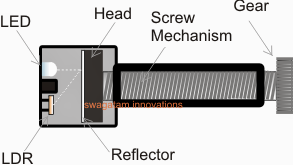
In the electromechanical set up demonstrated in the figure above you can easily observe the following incorporated components:
A small gear associated with a screw mechanism.
The head of the screw obtaining a white mat reflector surface
A LED/LDR assembly placed in front of the screw head.
How the Suggested mechanism functions.
The gear demonstrated in the above figure is usually to be locked with a different gear having a ratio which might be 10 times more than this gear.
The bigger gear really should be set up with the pedal mechanism such that it is linked to a rotational activity in accordance with the pressing of the pedal.
The rotational result from the gears will subsequently generate a forward motion of the screw head across the chamber where the LED/LDR assembly is situated.
The method may cause a correspondingly varying amount of shown light from the LED to be obtained by the LDR.
This varying data (by means of a varying resistance) in accordance with the pedal depression may be then provided to a signal processor circuit for enforcing the meant speed control of the specific vehicle.
Within the next submit we are going to understand the signal processor stage making use of PWM method.