


In this specific second section of the post we talk about the processor section for the offered pedal electric vehicle speed controller circuit.
In the earlier submit we understood a basic electromechanical converter assembly for converting the pedal action into a correspondingly varying electrical signal.
Within this article we research a circuit performance to be able to transform the pedal electric signal into a respectively varying PWM signal for the meant motor speed control of the vehicle.

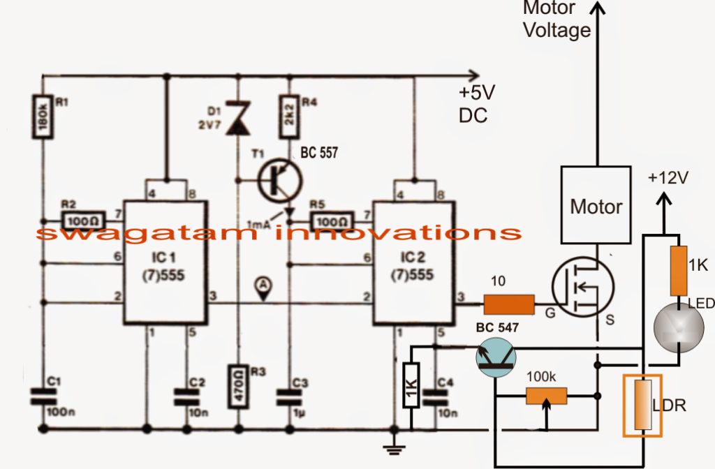
Making reference to the above circuit diagram we are able to determine the circuit operation with the aid of the following points:
IC1 is set up as a 80Hz pulse generator owning highest ON time and minimum OFF time as its duty cycle
IC2 is rigged as a comparator which first transforms the above 80Hz pulse utilized at its pin2 with triangle waves produced at its pin6 and compare the triangle waves with the modulating voltage offered at its pin5.
The pin5 modulating voltage is resulting from a BJT BC547 emitter that may be designed as an accepted collector with its base associated with the LDR inputs accomplished from the pedal behavior.
The varying resistances as a reaction to the pedal pressing is in a different way to the 100K preset setting and a proportionate magnitude of voltage is produced at the base of the transistor which changes the low current input into the same high current signal over pin5 of IC2.
This immediate potential level is approved and prepared by IC2 producing proportionate magnitude of PWM signals for the mosfet and the linked motor.
The motor speed is thus managed and varied according to the fluctuating PWMs in keeping with the pedal pressings of the vehicle.
The above methods successfully convert the pedal actions into a managed procedures of the vehicle motor and its speed.
The best way to Establish the Circuit.
It's very simple.
Press the pedal to its maximum point such that the screw head touches to the closest possible position in front of the LED/LDR assembly.
Next adjust the 100k preset until pin3 of the IC2 begins producing PWMs with maximum width, this might be established by assessing the voltage at pin3 to be as close as possible to the supply voltage of the circuit, that is 5V.
As soon as this is achieved, the establishing process could possibly be believed to be finalized.
The outcomes could possibly be now confirmed by pressing the pedal at different levels and checking the motor speed vary in an equivalent manner.
