


In this particular publish we are going to go through two ordinary externally activated timer circuits for two various application requirements.


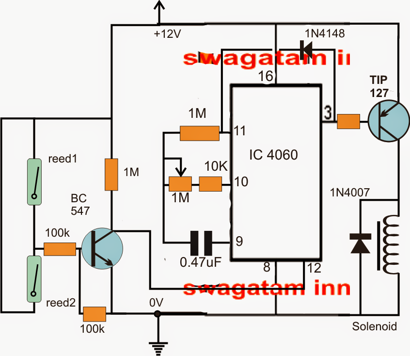
Talking about the diagram above the offered solenoid timer with reed switching can be viewed set up across a single timer/counter chip 4060.
Provided that the reed switches are not activated, the pin12 of the IC remains high by means of the 1M resistor, nevertheless if one or the other of the reed switches is activated, the BJT is forced to perform and ground pin12 of the IC which often becomes reset and causes the solenoid via the TIP127 transistor, the IC now starts counting. After 30 seconds (which can be varied or customized according to individual choice by means of the 1M pot), pin3 of the IC goes high leading to the TIP127 to deactivate on its own along with the solenoid.
The positive feedback by means of diode 1N4148 to pin11 ensures that the IC gets latched within this posture until the reed switch is produced and the IC gets reset to its original state.
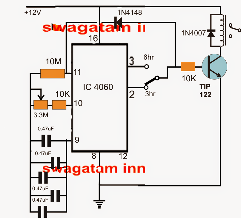
The 3/6 hour selectable timer circuit might be researched above. Once again a 4060 comes to the rescue and performs the application by including minimum variety of parts.
The IC is set up in its regular timer configuration.
The 3.3M pot together with the 0.47uF capacitors figure out the desired variable time interval across the demonstrated pinout 3 and 2.
The pin3 is placed to produce the necessary delay of 6 hours, so that pin2 enables to obtain a 50% less which is a 3 hour delay choice.
The above is properly chosen by means of a SPDT switch wired as demonstrated in the diagram.
The feedback diode guarantees a latching action which can be basically eradicated if a constant ON/OFf series is preferred by the user, forever.
