

Due to significant interest in this particular design, a simple non-regulated switching symmetric power supply with a high power output of 350W has been developed.
It employs a Half Bridge configuration without regulation.
This power supply serves as an alternative to standard power supplies used in audio amplifiers, as traditional transformers and electrolytic capacitors for power amplifiers tend to be costly and bulky.
Moreover, transformers are unsuitable for portable devices due to their weight. However, it should be noted that this simplicity comes at a cost, as a short circuit or overload can damage the MOSFETs and other components.
Additionally, MOSFETs may experience stress during power-up as they need to charge the output capacitors.
Circuit Description

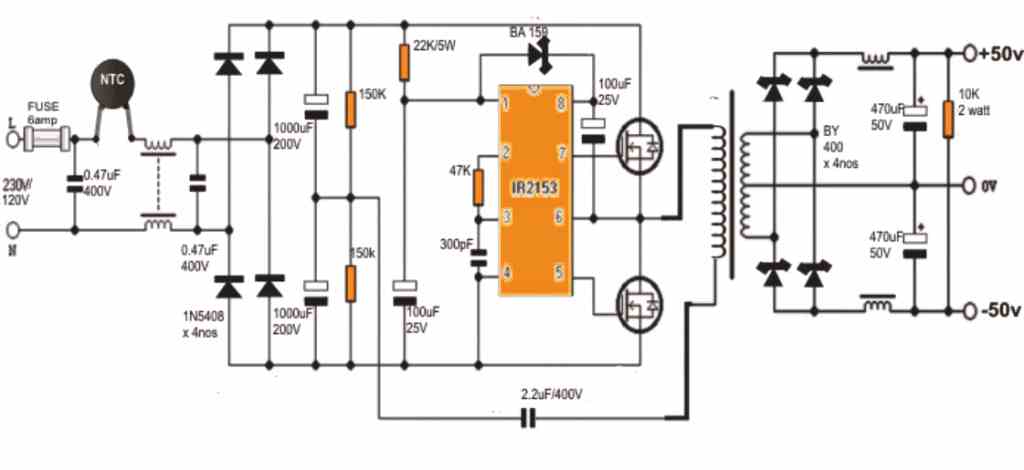
This very simple switch mode power supply circuit utilizes two N MOSFETs, driven by the integrated circuit IR2153.
Although this switching power supply lacks stabilization, it still provides a more stable and less noisy output voltage compared to a typical power supply, making it suitable for audio amplifiers.
The ripple at full load is less than 2V. To power the IR2153 circuit, a 27k 6W power resistor is employed. The built-in 15V Zener diode ensures voltage stabilization.
The operating frequency of the power supply is approximately 50kHz. To limit the peak current during capacitor charging, a thermistor is included at the input.
This thermistor can be salvaged from a faulty AT or ATX PC power supply. The transformer core is also sourced from any PC power supply.
Winding the Transformer
When winding the transformer, the primary winding is done first with 20 turns, followed by the secondary windings, and finally completing the rest of the primary winding.
This winding method minimizes leakage inductance, resulting in a more stable output voltage.
Adequate insulation must be maintained between the primary and secondary windings for safety reasons.
For increased safety, it is recommended to connect the output (i.e., center tap 0V) to the earth ground.
Chokes are incorporated to attenuate RF output ripple from the power supply.
The number of turns in the chokes is not critical, and various cores can be used, including those salvaged from PC power supplies.
To discharge the capacitors after switching off and prevent voltage spikes under no-load conditions, a 6k8 resistor is connected to the output.
Optionally, an LED can be connected in series with the resistor. The MOSFETs are mounted on a small heatsink, such as one sourced from a PC power supply, to dissipate heat effectively.