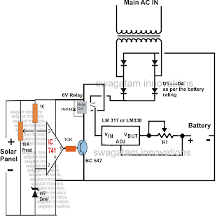
The mentioned automatic change over relay circuit is usually charges the attached battery at continuous current by means of the power caused by the solar panel, and reverts to DC power from an AC/DC adapter without the benefit of solar energy (throughout night time).
Taking a look at the suggested circuit diagram, we observe three simple phases, on the left an IC 741 circuit, at the center a voltage regulator phase utilizing IC LM317, while on the top an AC/DC adapter circuit.
The AC/DC adapter circuit is a basic improved transformer power supply, created for supplying 7V DC as far as there is certainly mains power accessible.
The IC317 circuit is a regulator circuit, set up for producing a continuing current, 7 volts output to the 6V battery which can be associated at the presented points.
The pot with the LM317 IC might be modified to generate the needed charging output for the specific battery.
The vital section of the circuit is the IC 741 phase, which happens to be establish as a high voltage trigger circuit.
The connected predetermined is altered such that the relay triggers when the solar panel voltage is above 7 volts.
The activation of the relay signifies the regulator circuit and the battery receive the voltage from the solar panel via the N/O contacts of the relay.
In spite of this, the time the panel voltage falls below 7 volts, the relay switches OFF, hooking up the DC adapter power with the regulator circuit, and now the battery begins getting charged by way of the AC/DC adapter voltage source.
R1 = Reference voltage/charging current = 1.25/Chg.Current
