

In this post we comprehensively discuss a few specialized circuits that can be used for charging any Li-Ion battrey correctly, and safely without any risk of damage to the battery.
Introduction
We're still a long way from the ultimate rechargeable battery. The proven Nicad (Nickel Cadmium or NiCd) cell has traditionally been recommended for high current applications. The so-called memory effect isn't any longer a factor with this sort of cell, according to extensive research.
Nicads cells are inexpensive in terms of price, however these have an ecological impact. Because these include the heavy metal cadmium, these must not be dumped in landfills at the end of their useful lives. As a result, Europe had pledged to end Nicad manufacturing until 1998. Nickel metal hydride (NiMH) cells are rapidly being viewed as a superior option.
These have the benefit of being free of toxic heavy metals and having a higher energy density (cell dimension to stored charge ratio). The Lithium-Ion (Li-Ion) cell is now the obvious victor in terms of energy density.
These are somewhat costly and susceptible to abuse, yet they happen to be the first option for applications like computers, video recorders, cell phones, and mobile gadgets wherein weight (lithium is the lightest existing element) and backup and battery size are crucial.
New advances have resulted in high-current cells that can operate automobiles and, in one example, a comprehensive aircraft with motorized assistance! Lange, a German aircraft maker, has used Li-Ion batteries to power their 'Antares' electric motor glider due to its light weight.
The prototype was designed for Ni-MH batteries, however switching to Li-Ion would provide the 500-pound plane an 885-foot-per-minute ascend rate, propelling the pilot to a height of almost 10,000 feet with its 57-horsepower (42-kilowatt) brushless electric engine.
Characteristics and Structure of Cells
We shall now investigate the cell's internal workings. The terminal voltage of Li-Ion is 3.6 or 3.7 V, which is a substantial benefit. This indicates that every single Li-Ion battery may be equivalent to 2 to 3 Ni-MH or Nicad cells (that have a cell voltage of 1.2 V).
A graphite anode and a lithium cobalt oxide or lithium manganese oxide cathode are immersed in an organically flowing electrolyte which includes absorbed lithium salt, which generates the lithium ions.
The cell potential of manganese oxide cathodes is 3.7 V, while that of cobalt oxide is 3.6 V . However, you may find Li-Ion cells maybe susceptible to inappropriate usage in this scenario.
The recharging voltage is 4.20 V for manganese oxide cathodes and 4.10 V for cobalt oxide cathodes in cells having manganese oxide cathodes.
Considering, the cell is not to be irreversibly destroyed, this voltage level should be kept under 50 mV. It's also crucial to keep the cell voltage above 2.4 or 2.5 V during discharge; else, the cell's life would be severely harmed.
The word 'Ion' existing with the battery's name merely means that Lithium must never be encountered in its metallic form in the battery. The electrolyte collects lithium ions (Li+) on the graphite anode throughout the charging process.
The dangers of incorrect usage
Li-Ion batteries are readily damaged by charging at too high a voltage. Internal gassing, overheating, and finally exploding might occur if the charging voltage is pushed over its optimal value of 4.1 V or 4.2 V. Even a 1% rise in voltage over this ideal level could induce the lithium ions in the cell to start converting to metallic lithium.
This, then, interacts strongly with water in the electrolyte, and consequently we should all retreat to a safe distance at this time rather than risk a direct confrontation with the cell explosion and its constituents. On the other hand, if the charging voltage is rather below the ideal level, the cell will be considerably undercharged.
A cell voltage level of about 100 mV below the optimal limit (4.2V) reduces the stored capacity by 7%. As if that weren't terrible enough, Li-Ion is also affected by how low the cell voltage is permitted to drop while discharging. Deep discharging a cell causes a fast and permanent loss of cell capacity.
Li-Ion batteries, as you may know, aren't the most fault-tolerant on the industry. Li-Ion cells are commonly used in specialized battery packs for specialized tools, such as laptops, mobile phones, and camcorders, when the hardware has been specifically developed to take a Li-Ion battery and proper charging devices has been ensured.
Battery Packs
To avoid wrong usage, Li-Ion battery packs are frequently equipped with some type of electrical protection. Figure 1 depicts various common designs. One of the easiest systems (Figure 1a) communicates cell temperature with the linked electronics through an in-built NTC sensor.


Figure 1b shows a rather more complex circuit that protects against overcharging and undercharging. In this design, the threshold voltage is detected by a protector IC, and the charge or discharge current could be prevented by shutting off MOSFET T2 or T1. To enable current to pass via the unswitched MOSFET, the intrinsic MOSFET body diode is employed in each scenario.

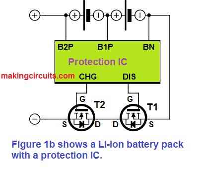
When both MOSFETs are turned off, the battery pack is completely disconnected. While charging and deep discharge, the Protector IC inhibits over-voltage. In idle state, the protector IC uses only about 1A.
A battery pack with a built-in battery management IC and a System Management Bus (SMB) interface is shown in Figure 1c. The IC uses Rsense, a low-resistance sense resistor (just few tens of milliohms), to monitor individual cell's voltage as well as the current drain.


This enables the control IC to assess how much charge is left in the battery pack and communicate that information to the device's charging circuit through the SMB two-wire interface's clock (SCL) and data (SDA) lines. Each cell in Li-Ion batteries also includes an over-pressure valve installed for safety purposes.
This permits pressure in the cell to be expelled to the air as a result of a high ambient temperature (– for example, a fire). The cell also has a low-resistance Positive Temperature Coefficient (PTC) circuit. When large currents are used, this component heats up, and its resistance rises, lowering the short circuit current.
How to Charge Lithium-ion battery Correctly
Recharging Li-Ion cells with a constant voltage and a current controlled source necessitates careful monitoring of the cell voltage. Improper charging might result in the complete loss of battery capacity or even death.
The charging device will measure the no-load cell potential at the start of a normal recharging cycle. If this value is less than 2.5 V, the cell is in a deep discharge state and will require a 'prequalification' charging period. This is accomplished by charging the cell at 5 mA until the voltage hits 2.5 V.
The charger will begin the rapid charging stage at around this voltage level. Until the cell voltage hits 4.1 V (for cobalt oxide) or 4.2 V (for manganese oxide), the current is restricted to 1C to 2C (where C denotes the Ah rating of the cell) .
The charger now enters the constant voltage phase, where it keeps the voltage (+/– 5 mV) and continuously checks the current until it decreases below a pre-determined threshold.
Once the charging current drops below 5% of the current supplied during the constant current phase, i.e. 0.05 C to 0.1 C, the top-off phase terminates. Now, the battery has been completely charged.
Pulsed charging with a voltage more than 4.2 V is allowed, provided the cell is not completely charged. It is required to utilize a couple of timers to restrict the charging times for safety concerns.
A rapid charging phase is restricted by one timer, while the overall charging time is limited by the other. The charging operation is interrupted and an error message suggesting a defective cell is delivered if the rapid charge timer runs out before the voltage hits 4.2 V.
If the 'total time' timer is not shut off during the normal schedule, the top-off phase will be terminated. Because Li-Ion cells exhibit an extremely reduced self-discharge, these do not demand a float charge; in fact, doing so would cause the cell to overcharge.
To keep the cell temperature within its operational range of +2°C to +45°C, an NTC sensor device is employed. When a cell overheats, the controller would stop the charging until the temperature settles down.
ICs for charging Lithium-Ion batteries
Figure 2 below depicts a straightforward charger for recharging single Li-Ion batteries.


The MAX 1679 (IC1) from MAXIM is at the core of the circuit. IC1 uses a pulsed waveform with a configurable markspace ratio to monitor the cell voltage at its BATT input and toggles MOSFET T1 such that the charging current from the constant current source supplied by IC2 and R1 may be regulated as required by the IC1.
T1 is always on during the rapid charge phase, and it is pulsed during the top-up phase. This IC's charging mechanism is quite similar to the charging method mentioned previously.
The IC MAX 1679 has a precision of lower than 1% for measuring cell voltage level. The charger's activity is shown via an LED (see Table 1). Once the charging process is completed, the Schottky diode D1 guarantees that the Li-Ion cell doesn't really discharge via the body diode of MOSFET T1.
To monitor the temperature of the cell, an NTC thermistor R3 is attached to the THERM input of IC1 and need to be in direct physical contact with the cell.
The ADJ input toggles an internal voltage reference, allowing you to choose between 4.2 V and 4.1 V for the terminal charging voltage, with regards to the battery type. R2 determines this voltage level selection.
Table 1
| LED state | Function |
| Flashing | Qualifying (Vbatt < 2.5V) |
| On | Charging (fast charging or top-off charging) |
| Flashing | Fast charging finished |
| Flashes every 3.5 s | Charging finished |
The maximum charging time is selected via the jumper at input TSEL (this time could be between 2.8 and 6.25 hours). The MAX 1679 would transition to low power mode at the finish of a charging process, using less than 1 amp from the battery. A main power module adapter could be used to make a cheaper Li-Ion charger.
Figure 3b depicts the output characteristic of a standard unregulated mains AC to DC adapter.

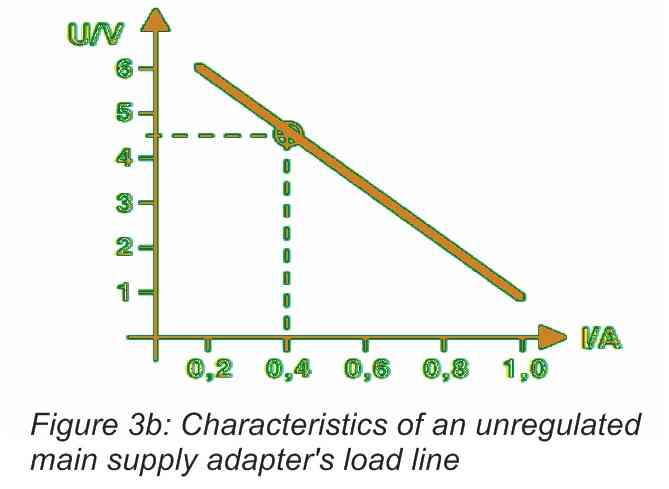
An ideal voltage source should actually have a flat load line, which means it should provide the same voltage regardless of load. Nevertheless, when the load current climbs, the output voltage of a standard unregulated mains AC to DC adapter drops due to the transformer winding resistance.
This feature is brought to excellent advantage in the circuit depicted in Figure 3a.

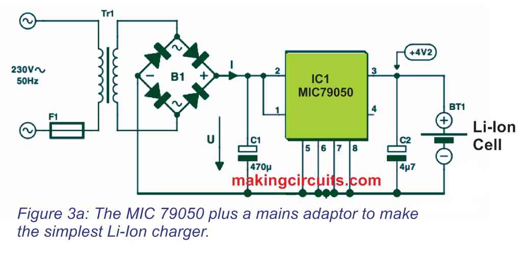
The transformer must deliver +4.5 V at a current of 0.5 to 1.0 times the cell's capacity in A/hr. This output current is 0.4 A in figure 3b. While the constant current charging phase is in progress, the battery is connected directly to the transformer's output.
Transformer impedance limits the charge current, and the cell voltage steadily increases. As soon as the cell voltage reaches 4.2 V, the MC79050 shifts to constant voltage charging and monitors the cell current until the cell is completely charged.
Using IC LM3622
Figure 4 depicts a Li-Ion charger circuit in accordance with the National Semiconductor IC LM 3622.

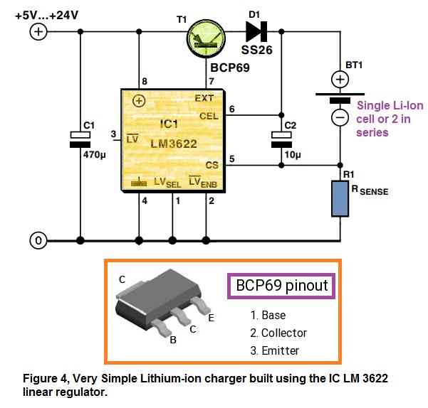
To regulate the voltage on the cell at 4.1 or 4.2 V, this design employs a PNP transistor as a linear regulator. The charging current is proportional to the value of Rsense and may be calculated using the following equation:
Charge current = 0.1 V / Rsense
To disperse the heat in transistor T1, a heatsink should be employed.