


The article clarifies a circuit which contains the potential to correct or transform an individuals unique voice into a whole new form.
The quality tone of every single individuals voice is especially one of a kind in all conditions. How frequently we get a phone call and just by simply listening our interlocutor has the ability to realize right away who it is on the other side.
In a number of situations we can manage to understand the occurrence of an individual in a group or in a special event simply by hearing to his or her voice, without even observing the individual.
Do you think you would be interested to change the timbre of a person's voice at will and make it tend to be unique to other people? Or modify it even like a robot or a being from some another planet?
The planned digital voice changer circuit is merely created to make this happen for you, and quite much more.
In accordance with a voice modulator technology from HOLTEK, this voice changer chip digitally processes the fed voice signal all the time.
It does this by shifting the frequency spectrum involved with the voice therewith, upwards or downwards in seven incremental actions as well as the accompanying output is discovered as comparatively much thinner or thicker in its frequency.
The consequence could be compared to that gained a playback speed of a vocal information recorded on a tape is increased or decreased, except that it does without influencing or distorting the sped of the speech, in addition on top of that it contributes two specific sound effects: vibrato and robot to a sample speech.
The first function along with the two converts your voice with more tremulous while the second has impact on it simulating a robot kind of voice.
On the other hand under both the outputs the voice is fed to the IC by way of a typical electret microphone and the dimensioned output is reproduced by way of a dynamic speaker.
The whole system functions from a 9V battery.
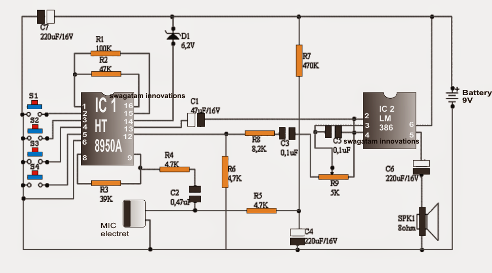
The HT8950 consists of, among other efficient blocks of an amplifier with internal polarization microphone, an A / D of 8 bits, a static RAM (SRAM) and a D / A converter 8 bits. The A / D and D / A work at a sampling rate of 8Khz, good enough to protect the spectrum of the human voice (3Khz) and delivers an output quality and quite high signal to noise ratio (SNR).The following table summarizes the function of each pin for HT8950A version.No. NAME FUNCTION1 OSC1 input of the oscillator2 VIB input mode selector vibrato3 TGU step input selector UP4 TGD input selector step DOWN5 ROB Input Selector mode step ROBOT6 VSS negative supply line (GND)7 NC Not connected8 A0 output internal amplifier9 AIN input of the internal amplifier10 VDD Positive Power Line11 LED LAMP Output for volume12 AUDIO Audio Output13 VREF Reference voltage internal amplifier14 TS chip test input15 FVIB control output frequency vibrato16 OSC2 output of the oscillatorIn Figure 2, the schematic diagram of the digital voice changer proven. The system is composed generally of a digital voice modulator and an audio amplifier, produced around respectively the chip IC1 (HT8950A) and IC2 (LM386I) the user's voice is grabbed by an electret microphone (MIC1) and reproduced generally or frequency offset in a dynamic speaker (SPK1). The complete assembly runs from a 9V battery (B1).
After being caught by the microphone, the voice signal is employed on the internal amplifier HT8950 by way of R4 C2 network. The voltage achieve of this amplifier, that may be an open loop is normally comparable to 2000, established R3 (feedback resistor) and R4 (input resistance), being of the order of 8.3 times.
Resistors R5 and R7, as well as the capacitor C4, the biasing circumstances render the electret element.
An amplified and limited in bandwidth time, the injected HT8950 voice signal to the A / D bits where internal 8 is digitized at a nominal sampling rate of 8Khz. The sampling signal generator delivers a time base, in turn regulated by an oscillator.
The frequency of the latter, which is about 512Khz, would depend on R2.After digitized voice signal is stored in a static RAM (SRAM), also regulated by the time base generator, a control circuit pulls info from the RAM and transferred to a latching register.
From the latter, the speech signal goes to a D / A converter the 8-bit reset to its original analog form or shifted frequency spectrum. This signal can be acquired on the AUDIO output (pin 12).
Depending on the speed with which the SRAM data to the D / A are supplied, the original signal is reproduced with or without offset frequency spectrum.
This problem varies according to the elected step by push-button switches S2 type (UP) and S3 (DOWN). Specially, with every touch, move the speech spectrum S2 step up and S3 moves it a step down. In both situations, the series is constantly sustained, as proven in Figure 3.
Once changed to its analog form, the speech signal is carried out through C3 R8-network to a LM386 (IC2) amplifier, liable for helping the speaker (SPK1) which make it audible.
The resistor R6 plays the role of a pull-down of the D / A HT8950 internal current mode and trimmer R9 as master volume control system.
Other equipment understand auxiliary capabilities. D1 specially controls the supply voltage to a safe value HT8950 (below 2.8V) and R1 vibrato frequency fixed at 8 Hz, an estimated.
List of Materials
Resistance (1 / 4W 5%)
R1-100K
R2-47K
R3-39K
R4, R5, R6-4,7K
R7-470
R8-8,2K
R9-5K, Trimmer, 1 lap
Capacitors
C1-4,7uF / 16V electrolytic
C2-0,47uF (474), ceramic
C3, C5-0,1uF (104), ceramic.
C4, C6, C7-220uF / 16V, electrolytic.
Semiconductors
Zener diode D1-6,2V / 0.5W
Integrated CircuitsModulator voice IC1- HT8950A
IC2- LM386 audio amplifier
Transducers MIC1- electret microphone, miniature
SPK1- Speaker 8 / 0.25W
Electromechanical
S1,..., S4-push-button switches Miniature NAJ1- type connector for 9V battery snap.