In this publish we go through concerning a automatic fan speed regulator circuit for handling the temperature of a heatsink and from avoiding the temperature to erach risky phases. This process is always to make certain safeguardign of the hooked up devices wit the heatsink.
By making use of this circuit the speed of a fan motor elf adjusts dependent on the temperature of a heatsink which may be supposed to be regulated. Listed here a normal thermistor device is employed as the temperature sensor selected with a resistance value of 10 K at 25 degrees ambient temperature.
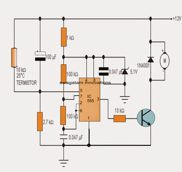
The motor to be regulated is supported by the PWM pulses from the IC 555 whose pulse rate cycle falls from around 34% at room temperature (minimum speed) to 100% (maximum speed) when the temperature has achieved a high. These kinds of pulses are created by 555 that may be rigged to work as an integrated voltage regulated oscillator circuit. On the control voltage pin 5 a ranging voltage is utilized dependent upon the durability of the thermistor which usually varies according to the temperature created over the heat sink.
That allows you to make certain a quick transfer of temperature, the thermistor needs to be linked or stuck to the heatsink correctly. The shown 100uF capacitor attached in equal with the thermistor shorts the supply with pin5 of the IC simulating a higher temperature status for some seconds in the course of power activate in order that the motor gets an initialization torque and is stopped from acquiring stalled.
The voltage to the IC 555 is managed by the zener diode of 9,1V in order that it enables the IC to perform irrespective of the input supply variations.
To adjust the temperature activating threshold exactly where the motor could be supposed to increase, you can actually change the value 2.7K resistor hooked up to pin 5 of 555 or perhaps apply a potentiometer for creating the exact same.